Cable installation in ac-
cordance with EMC
Signal and fieldbus cables are susceptible to interference. Motor cables are
interference sources.
●
Lay cables being susceptible to interference or sources of interference at the
highest possible distance from each other.
●
The interference immunity of signal and fieldbus cables increases if the cables
are laid close to the earth potential.
●
If possible, avoid laying long cables and make sure that they are installed in
areas being subject to low interference.
●
Avoid parallel paths with little cable distance of cables being either susceptible
to interference or interference sources.
HART cable recommend-
ation:
Twisted wire pair, shielded.
For cable length <1,500 m: Cross section min. 0.2 mm²
For cable length >1,500 m: Cross section min. 0.5 mm²
Multiple-twisted pair cables must not be used.
Prior to installation, please note:
●
Connection is made as point-to-point topology.
●
Respect a distance of minimum 20 cm between HART cables and other cables
if possible. The cables should be laid in a separate, conductive, and earthed
cable tray, if possible.
●
Make sure that there are no potential differences between participants.
●
Maximum cable length depends on characteristics of devices connected (im-
pedance), of cables used (cable capacity and resistance) and the impedance
of all devices installed between two end devices.
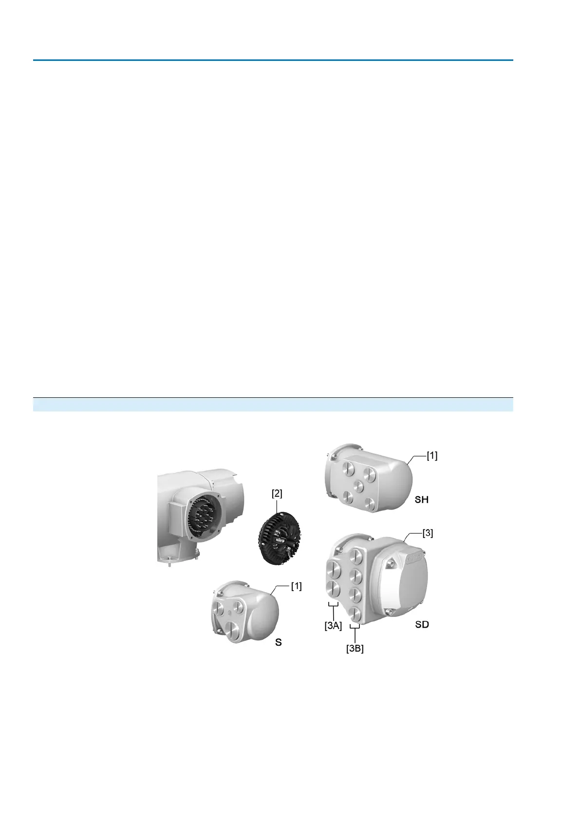
5.2. S/SH/SD electrical connection (AUMA plug/socket connector)
Figure 18: S, SH and SD electrical connection
[1] Cover
[2] Socket carrier with screw-type terminals
[3] Terminal compartment (in cover)
[3A] Cable entries for mains connection (pins for motor and pins for controls)
[3B] Cable entries for HART cables
Short description
Plug-in electrical connection with screw-type terminals for pins for motor and pins
for controls. Pins for controls also available as crimp-type connection as an option.
24
SA 07.2 – SA 16.2/SAR 07.2 – SAR 16.2 Control unit: electronic (MWG)
Electrical connection AC 01.2 Non-Intrusive HART

 Loading...


