4. Assembly
4.1. Mounting position
The product described in this document can be operated without restriction in any
mounting position.
4.2. Handwheel fitting
Information For transport reason, handwheels with a diameter 15.7 inches (400 mm) and larger are
supplied separately within the scope of delivery.
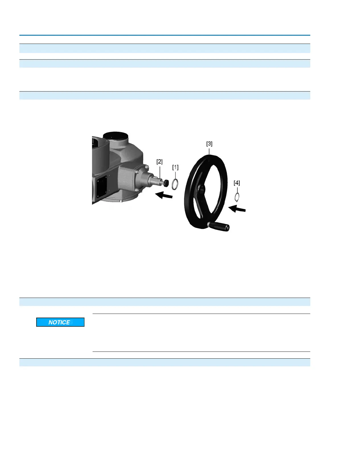
Figure 5: Handwheel
[1] Spacer
[2] Input shaft
[3] Handwheel
[4] Retaining ring
1. If required, fit spacer [1] onto input shaft [2].
2. Slip handwheel [3] onto input shaft.
3. Secure handwheel [3] using the retaining ring [4] supplied.
4.3. Multi-turn actuator: mount to valve/gearbox
Danger of corrosion due to damage to paint finish and condensation!
→
Touch up damage to paint finish after work on the device.
→
After mounting, connect the device immediately to electrical mains to ensure that
heater minimizes condensation.
4.3.1. Output drive type A
Application
●
Output drive for rising, non-rotating valve stem
●
Capable of withstanding thrust
Design
Output mounting flange [1] with axial bearing stem nut [2] form one unit.Torque is
transmitted to valve stem [3] via stem nut [2].
12
SAEx 07.2 – SAEx 16.2 / SAREx 07.2 – SAREx 16.2
Assembly
 Loading...