2. Remove stem nut [1] together with axial needle roller bearings [2].
3. Remove axial bearing washers [2.1] and axial needle roller and cage assemblies
[2.2] from stem nut [1].
4. Drill and bore stem nut [1] and cut thread.
Information: When fixing in the chuck, make sure stem nut runs true!
5. Clean the machined stem nut [1].
6. Apply sufficient suitable EP multi-purpose grease to axial needle roller and cage
assemblies [2.2] and axial bearing washers [2.1], ensuring that all hollow spaces
are filled with grease.
7. Place greased axial needle roller and cage assemblies [2.2] and axial bearing
washers [2.1] onto stem nut [1].
8. Re-insert stem nut [1] with bearings [2] into output drive.
Information: Ensure that dogs or splines are placed correctly in the keyway of the
hollow shaft.
9. Screw in spigot ring [3] until it is firm against the shoulder.
4.3.1.2. Multi-turn actuator (with output drive type A): mount to valve
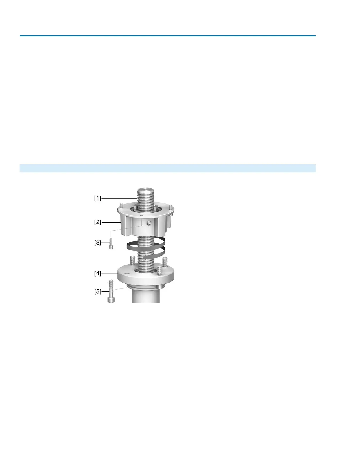
Figure 8: Assembly of output drive type A
[1] Valve stem
[2] Output drive type A
[3] Screws to actuator
[4] Valve flange
[5] Screws to output drive
1. If the output drive type A is already mounted to the multi-turn actuator: Remove
screws [3] and remove output drive type A [2].
2. Check if the flange of output drive type A matches the valve flange [4].
3. Apply a small quantity of grease to the valve stem [1].
4. Place output drive type A on valve stem and turn until it is flush on the valve flange.
5. Turn output drive type A until alignment of the mounting holes.
6. Screw in fastening screws [5], however do not completely tighten.
7. Fit multi-turn actuator on the valve stem so that the stem nut dogs engage into the
output drive sleeve.
➥
The flanges are flush with each other if properly engaged.
14
SAEx 07.2 – SAEx 16.2 / SAREx 07.2 – SAREx 16.2
Assembly
 Loading...