10. Corrective action
10.1. Faults during commissioning
Table 11:
Faults during commissioning
RemedyDescription/causeFault
Exchange reduction gearing.Reduction gearing is not suitable for turns/stroke of
the actuator.
Mechanical position indicator cannot
be set.
●
Determine overrun: Overrun = travel covered
from switching off until complete standstill.
●
Set limit switches again considering the overrun
(turn handwheel back by the amount of the
overrun).
The overrun was not considered when setting the
limit switches.
The overrun is generated by the inertia of both the
actuator and the valve and the delay time of the
controls.
In spite of correct limit switch setting,
actuator operated into the valve end
position.
●
Connect link across RWG to XK (terminals 23/24)
●
Connect external load to XK, e.g. remote indica-
tion.
●
Observe maximum load R
B
.
Current loop across RWG is open.
(Position feedback 0/4 – 20 mA is only possible if the
current loop is closed across the RWG.)
No value can be measured at measur-
ing points of the RWG.
Exchange reduction gearing.Reduction gearing is not suitable for turns/stroke of
the actuator.
Measuring range 0/4 – 20 mA or maxi-
mum value 20 mA at position transmit-
ter cannot be set or supplies an incor-
rect value.
Call service.The LED on the EWG either flashes in setting mode
a) single flash or b) triple flash:
a) EWG is not calibrated.
b) Magnet positions of EWG are not aligned.
The measuring range 0/4 – 20 mA at
EWG position transmitter cannot be
set.
Check setting, if required, reset end positions.
Refer to <Check switches> and replace the switches
if required.
Switch is defective or switch setting is incorrect.Limit and/or torque switches do not trip.
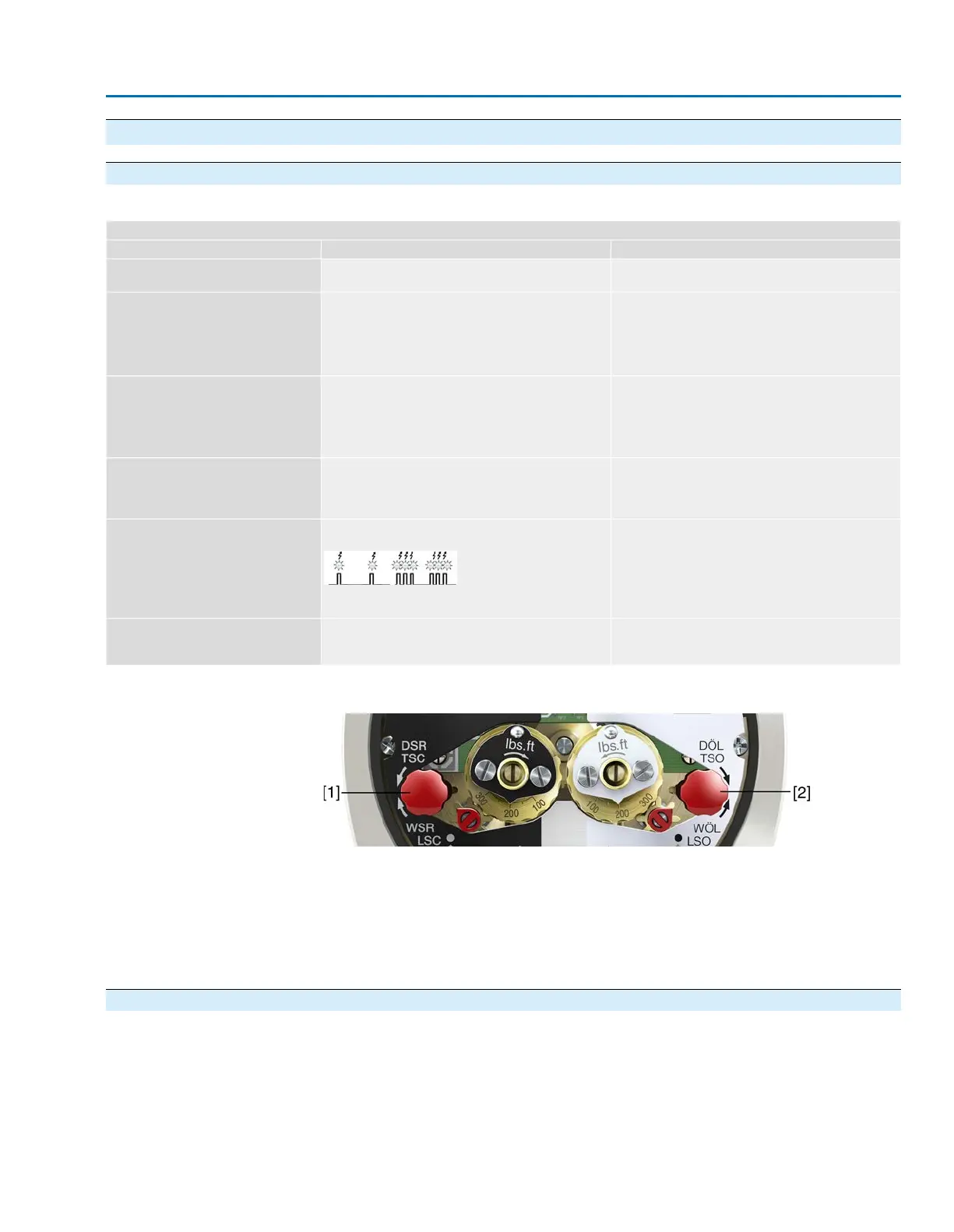
Switch check
The red test buttons [1] and [2] are used for manual operation of the switches:
1. Turn test button [1] in direction of the TSC arrow:Torque switch CLOSED trips.
3. Turn test button [2] in direction of the TSO arrow:Torque switch OPEN trips.
If the actuator is equipped with DUO limit switches (option), the intermediate position
switches (LSA and LSB) will be operated at the same time as the torque switches.
1. Turn test button [1] in direction of the LSC arrow: Limit switch CLOSED trips.
2. Turn test button [2] in direction of the LSO arrow: Limit switch OPEN trips.
10.2. Motor protection (thermal monitoring)
In order to protect against overheating and impermissibly high temperatures at the
actuator, thermal switches are embedded in the motor winding.They trip as soon as the
max. permissible winding temperature has been reached.
Behavior during failure
If the signals are correctly wired within the controls, the actuator is stopped and can only
resume its operation once the motor has cooled down.
41
SAEx 07.2 – SAEx 16.2 / SAREx 07.2 – SAREx 16.2
Corrective action
 Loading...