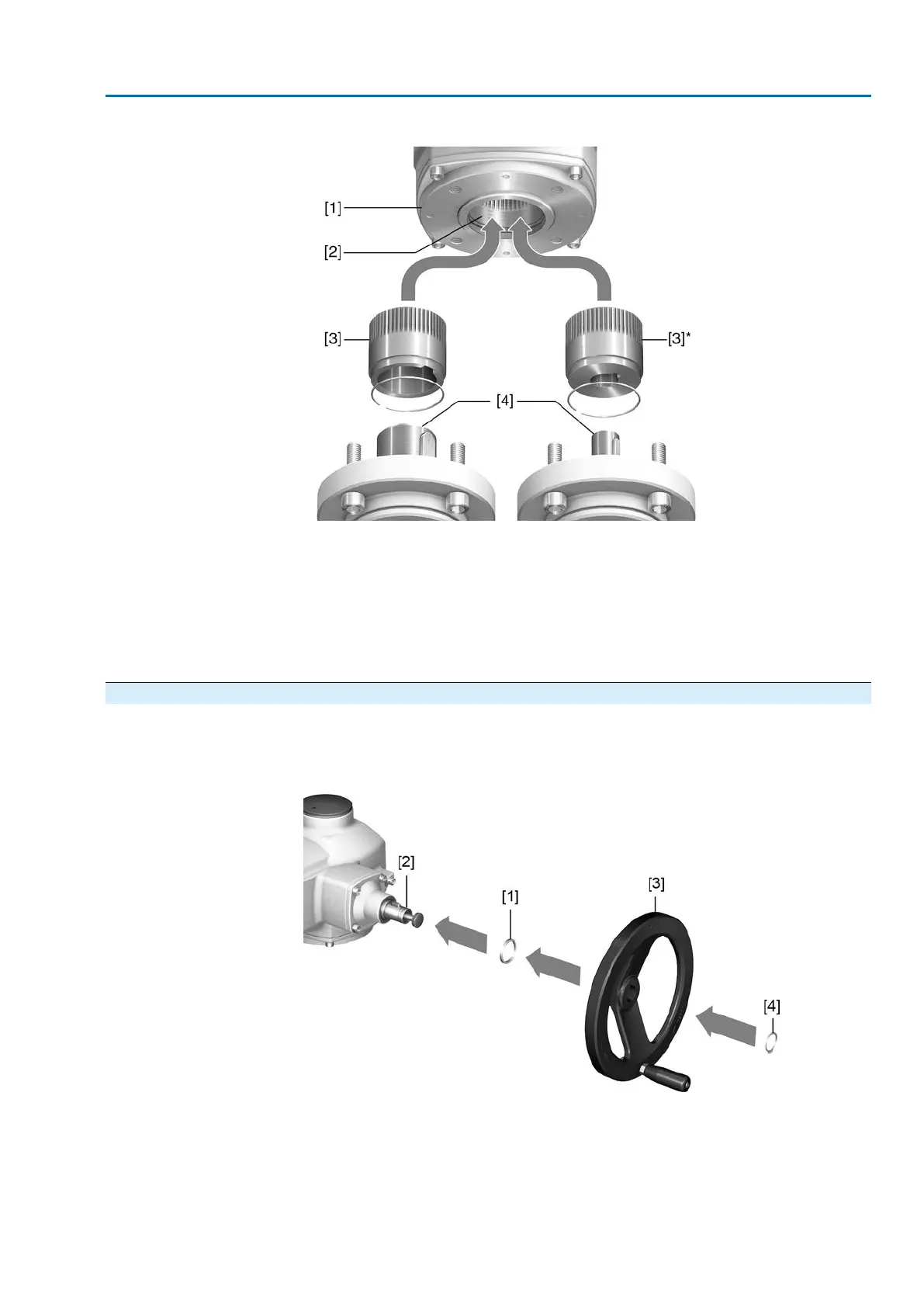
Figure 9: Output drive type B
[1] Flange multi-turn actuator (e.g. F07)
[2] Hollow shaft
[3] Output drive sleeve (illustration examples)
[3] B/B1/B2 and [3]* B3/B4/E, respectively with bore and keyway
[4] Gearbox/valve shaft with parallel key
Information
Spigot at valve flanges should be loose fit.
4.3. Handwheel fitting
For transport reasons, handwheels with a diameter of 400 mm and larger are supplied
separately within the scope of delivery.
Figure 10: Handwheel
[1] Spacer
[2] Input shaft
[3] Handwheel
[4] Retaining ring
1. If required, fit spacer [1] on input shaft [2].
17
SA 07.2 – SA 16.2 / SAR 07.2 – SAR 16.2 Control unit: electronic (MWG)
AC 01.2 Non-Intrusive EtherNet/IP Assembly

 Loading...


