4.
Hold lower indicator disc in position and turn upper disc with symbol (OPEN)
until it is in alignment with the mark on the cover.
5. Move valve to end position CLOSED again.
6. Check settings:
If the symbol (CLOSED) is no longer in alignment with mark on the cover:
6.1 Repeat setting procedure.
6.2 Test/set gear stage of the reduction gearing.
10.3.2. Gear stage of the reduction gearing: test/set
This test/setting is only required if the turns/stroke of the actuator were changed at
a later date.The control unit may possibly have to be exchanged:
Information The adjustable stroke range is indicated on the order data sheet (e.g. “1 – 500
turns/stroke”).
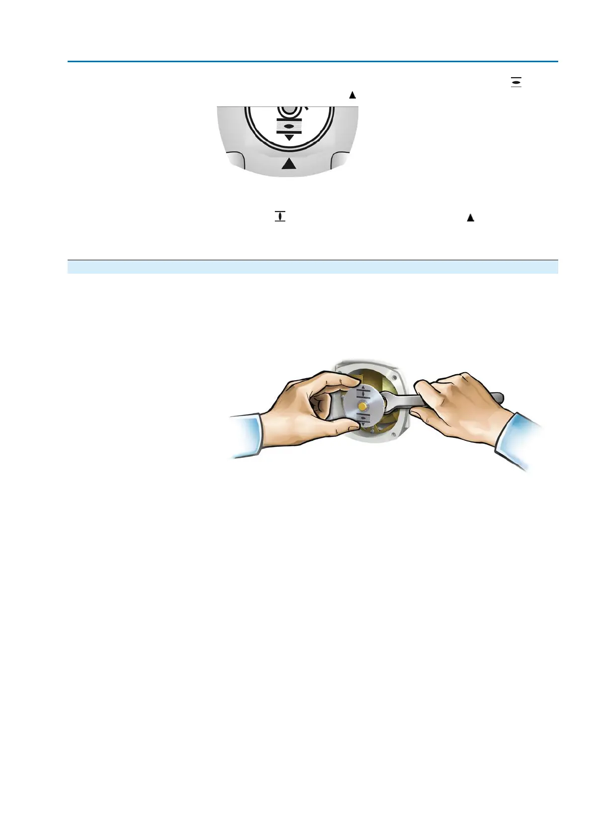
1. Pull off indicator disc using a spanner as lever if required.
71
SA 07.2 – SA 16.2 / SAR 07.2 – SAR 16.2 Control unit: electronic (MWG)
AC 01.2 Non-Intrusive EtherNet/IP Commissioning (settings/options in the actuator)

 Loading...


