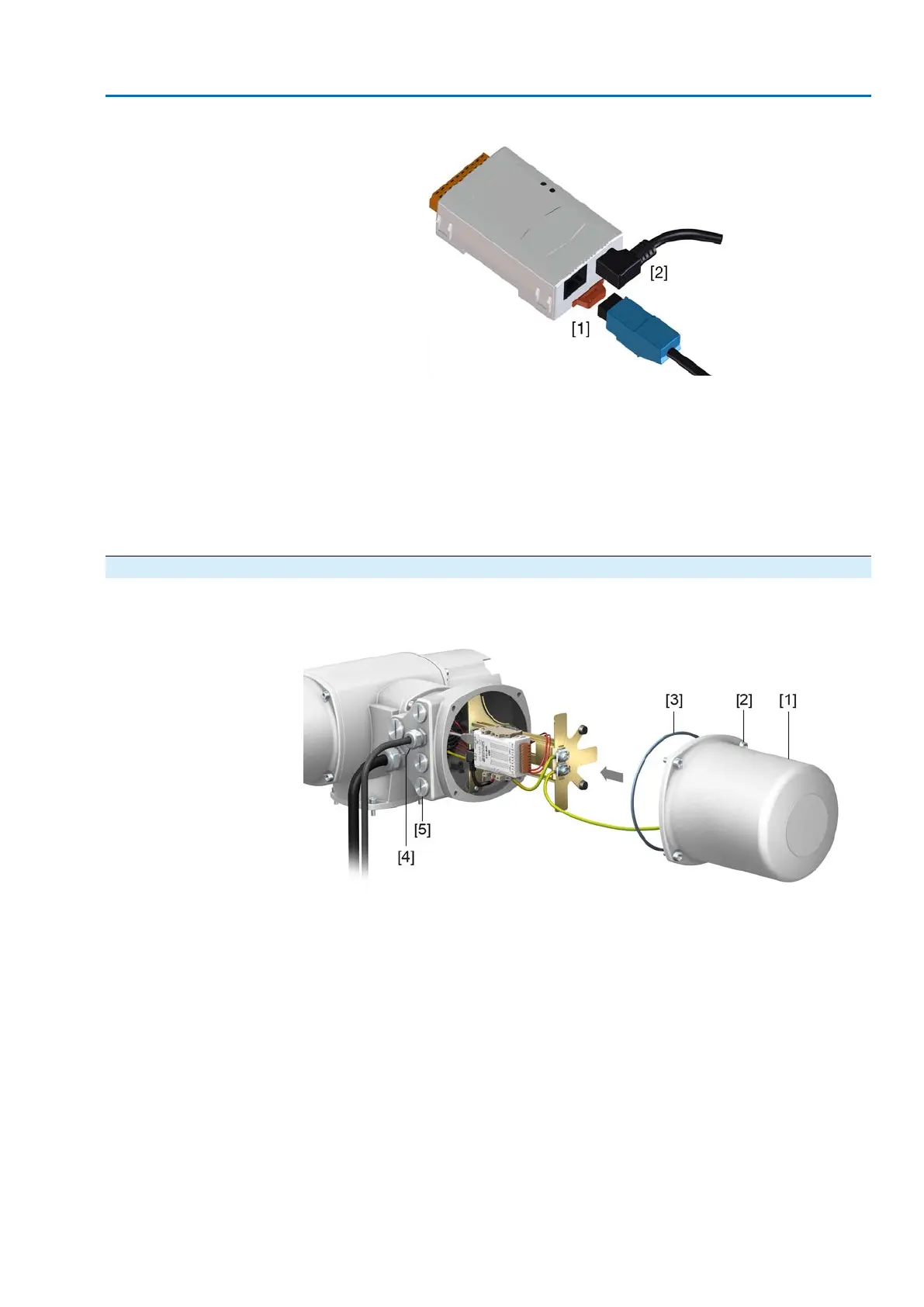
Figure 25: EtherNet/IP module
[1] RJ-45 plug-in socket for connecting the Industrial Ethernet cable
[2] Power supply
Cable connection
1. For connecting cables to RJ-45 connectors, proceed in compliance with the
connector manufacturer specifications.
➥
When using the RJ-45 connector supplied by AUMA, please heed the assembly
instructions provided.
2. Connect RJ-45 connector to port for Ethernet cable [1].
5.3.6. Fieldbus terminal compartment: close
Figure 26: Close fieldbus terminal compartment
[1] Cover (fieldbus terminal compartment)
[2] Screws for cover
[3] O-ring
[4] Cable entries for fieldbus cables
[5] Blanking plug
1. Clean sealing faces of cover [1] and housing.
2. Apply a thin film of non-acidic grease (e.g. petroleum jelly) to the sealing faces.
3. Check whether O-ring [3] is in good condition, correctly insert O-ring.
4. Fit cover [1] and fasten screws [2] evenly crosswise.
5. Fasten cable glands and blanking plugs applying the specified torque to ensure
the required enclosure protection.
31
SA 07.2 – SA 16.2 / SAR 07.2 – SAR 16.2 Control unit: electronic (MWG)
AC 01.2 Non-Intrusive EtherNet/IP Electrical connection

 Loading...


