4.3.1 Coupling
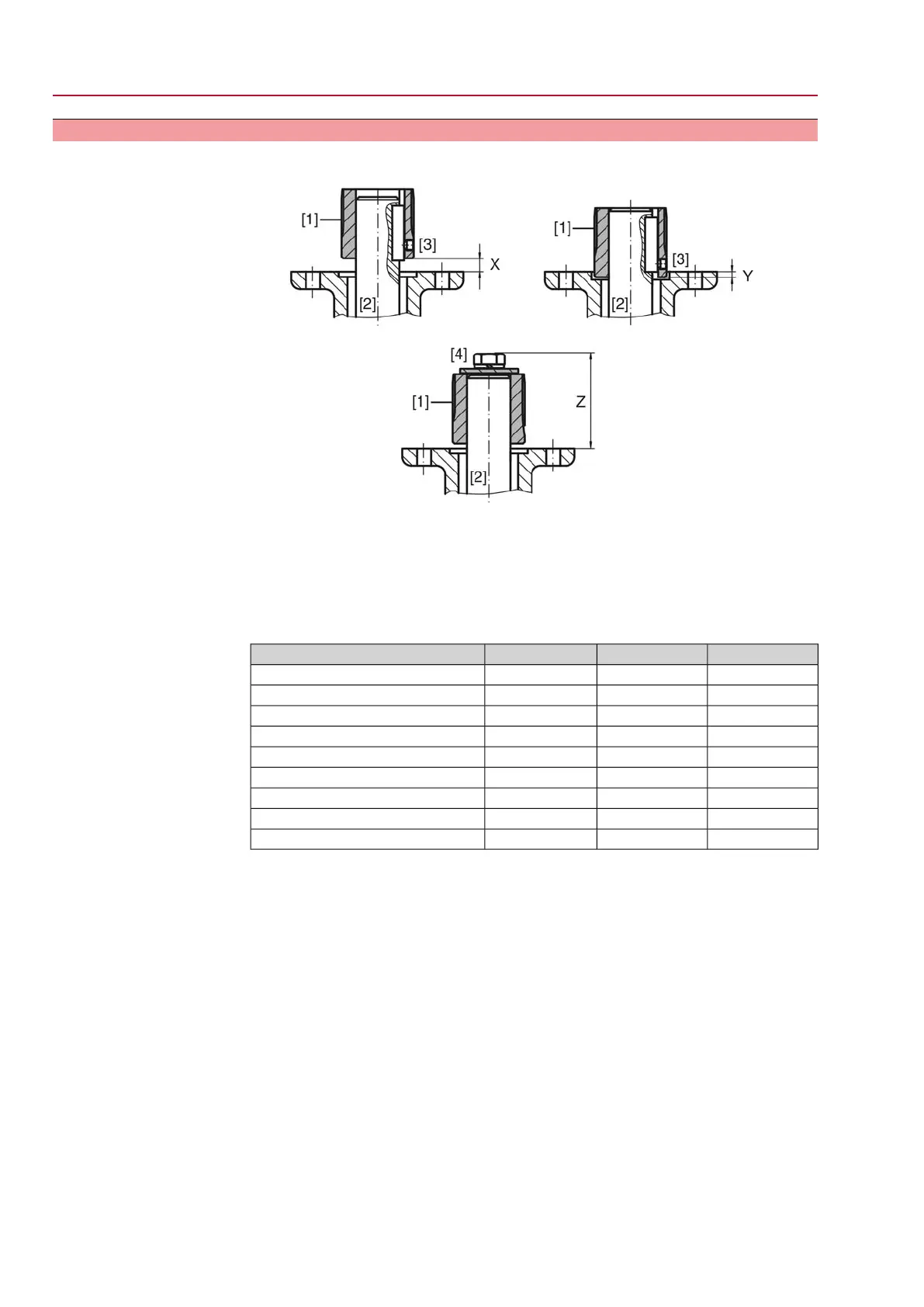
Figure 6: Coupling fitting dimensions
[1] Coupling
[2] Valve shaft
[3] Grub screw
[4] Screw
Table 1: Coupling fitting dimensions
Z max [mm]Y max [mm]X max [mm]Type, size - mounting flange
60–9SG/SGR 05.1-F05
60–9SG/SGR 05.1-F07
60–9SG/SGR 07.1-F07
75–24SG/SGR 07.1-F10
77915SG/SGR 10.1-F10
97–32SG/SGR 10.1-F12
100–25SG/SGR 12.1-F12
120–45SG/SGR 12.1-F14
132–57SG/SGR 12.1-F16
1. Use handwheel to drive actuator to mechanical end stop.
Information: Assemble valve and actuator in the same end position.
- With butterfly valves: recommended mounting position is end position
CLOSED.
- With ball valves: recommended mounting position is end position OPEN.
2. Thoroughly degrease mounting faces of the mounting flange.
3. Apply a small quantity of grease to the valve shaft [2].
4. Place coupling [1] onto valve shaft [2] and secure against axial slipping by using
a grub screw, a circlip or a screw.Thereby, ensure that dimensions X, Y or Z
are observed (refer to figure and table <Coupling fitting dimensions>).
5. Apply non-acidic grease at splines of coupling.
6. Fit actuator.
Information: Ensure that the spigot (if provided) fits uniformly in the recess
and that the flanges are in complete contact.
7. If flange bores do not match thread:
7.1 Slightly rotate handwheel until bores line up.
7.2 If required, shift actuator position by one tooth on the coupling.
12
SG 05.1 – SG 12.1/SGR 05.1 – SGR 12.1 Control unit: electronic (MWG)
Assembly AC 01.1 Non-Intrusive Modbus RTU

 Loading...


