8. Fasten actuator with screws [4].
Information:We recommend glueing the screws using sealing material to avoid
contact corrosion.
→
Fasten screws [4] crosswise with a torque according to table:
Table 2: Tightening torques for screws
Tightening torque T
A
[Nm]Screws
Thread
Strength class 8.8
11M6
25M8
51M10
87M12
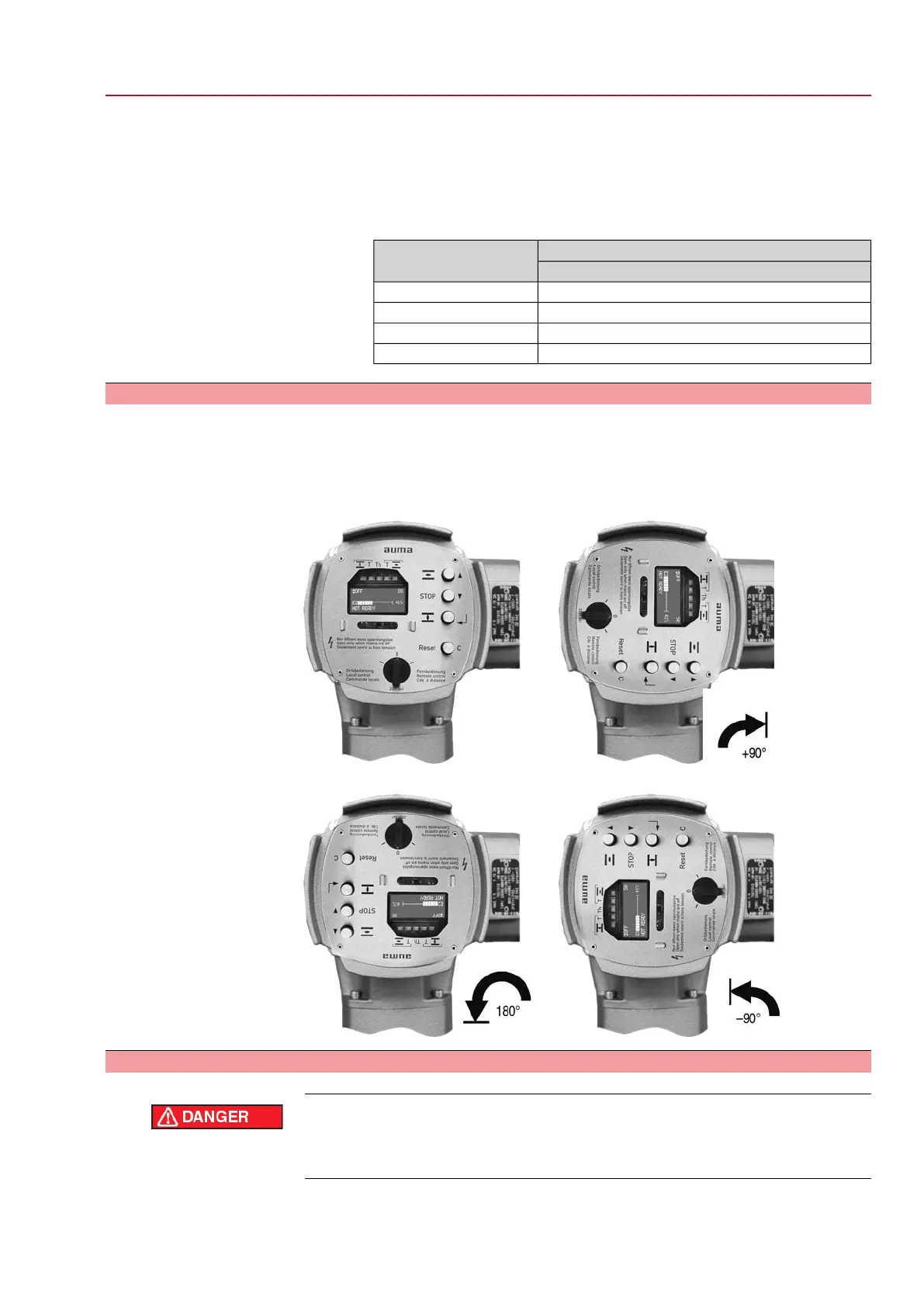
4.4 Mounting positions of local controls
The mounting position of the local controls is selected according to the order. If, after
mounting the actuator to the valve or the gearbox on site, the local controls are in
an unfavourable position, the mounting position can be changed at a later date. Four
mounting positions are possible.
Figure 7: Mounting positions A-2 and B-2
Figure 8: Mounting positions C-2 and D-2
4.4.1 Mounting positions: modify
Hazardous voltage!
Risk of electric shock.
→
Disconnect device from the mains before opening.
1. Loosen screws and remove the local controls.
2. Check whether O-ring is in good condition, correctly insert O-ring.
13
SG 05.1 – SG 12.1/SGR 05.1 – SGR 12.1 Control unit: electronic (MWG)
AC 01.1 Non-Intrusive Modbus RTU Assembly

 Loading...


