5.2 Connection with AUMA plug/socket connector
Cross sections AUMA plug/socket connector:
●
Power terminals (U1, V1, W1, U2, V2, W2): max. 6 mm² flexible/10 mm² solid
●
PE connection : max. 6 mm² flexible/10 mm² solid
●
Control contacts (1 to 50): max. 2.5 mm²
5.2.1 Terminal compartment: open
Information The bus connection can be separately accessed from the mains connection (refer
to <Bus terminal compartment: open>).
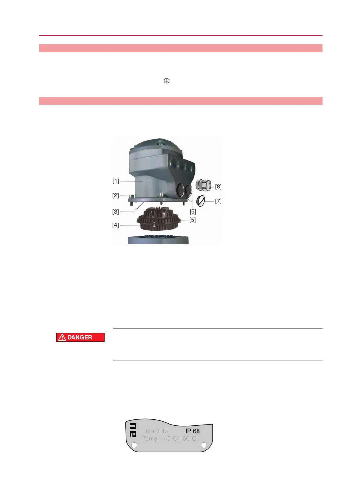
Figure 10: Mains connection AUMA plug/socket connector SD bus
[1] Connection housing
[2] Screws for connection housing
[3] O-ring
[4] Screws for socket carrier
[5] Socket carrier
[6] Cable entry for mains
[7] Blanking plug
[8] Cable gland (not included in delivery)
Information Bus operation is not interrupted when removing the connection housing [1].
Hazardous voltage!
Risk of electric shock.
→
Disconnect device from the mains before opening.
1. Loosen screws [2] and remove connection housing [1].
2. Loosen screws [4] and remove socket carrier [5] from connection housing [1].
3. Insert cable glands [8] suitable for connecting cables.
➥
The enclosure protection IP... stated on the name plate is only ensured if suitable
cable glands are used. Example: Name plate shows enclosure protection IP
68.
17
SG 05.1 – SG 12.1/SGR 05.1 – SGR 12.1 Control unit: electronic (MWG)
AC 01.1 Non-Intrusive Modbus RTU Electrical connection

 Loading...


