●
If possible, avoid laying long cables and make sure that they are installed in
areas being subject to low interference.
●
Avoid long parallel paths with cables being either susceptible to interference or
interference sources.
●
For the connection of remote position transmitters, screened cables must be
used.
Type of current, mains
voltage and mains fre-
quency
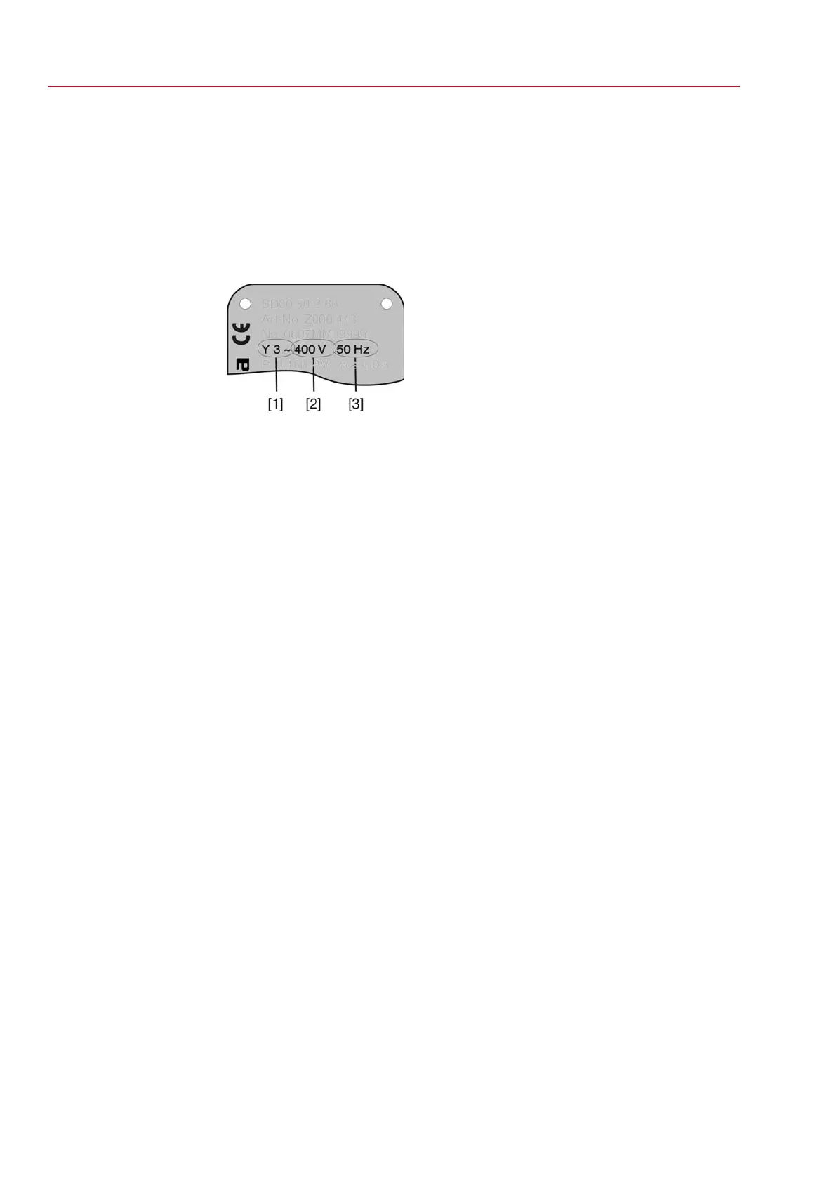
Type of current, mains voltage and mains frequency must match the data on the
motor name plate.
Figure 9: Motor name plate (example)
[1] Type of current
[2] Mains voltage
[3] Mains frequency (for 3-ph and 1-ph AC motors)
Connecting cables
●
For device insulation, appropriate (voltage-proof) cables must be used. Specify
cables for the highest occurring rated voltage.
●
Use connecting cable with appropriate minimum rated temperature.
●
For connecting cables exposed to UV radiation (outdoor installation), use UV
resistant cables.
Bus cables
Only cables complying with the recommendations of EIA 485 specifications should
be used for Modbus wiring.
Cable recommendation:
Impedance:
135 to 165 Ohm, at a measurement frequency bet-
ween 3 and 20 MHz
Cable capacity:
< 30 pF per metre
Wire diameter
> 0.64 mm
Wire cross section:
0.34 mm², corresponds to AWG 22
Loop resistance:
< 110 Ohm per km
Screening:
CU shielding braid or shielding braid and shielding
foil
Prior to installation, please note:
●
Connect maximum 32 devices to one segment.
●
If more devices are to be connected:
- Connect several segments using repeaters.
●
Respect a distance of minimum 20 cm between the bus cable and other cables.
●
If possible, bus cables should be laid in a separate, conductive, and earthed
cable tray.
●
Make sure to avoid potential differences between the individual devices on the
bus (perform an equipotential earth bonding).
16
SG 05.1 – SG 12.1/SGR 05.1 – SGR 12.1 Control unit: electronic (MWG)
Electrical connection AC 01.1 Non-Intrusive Modbus RTU

 Loading...


