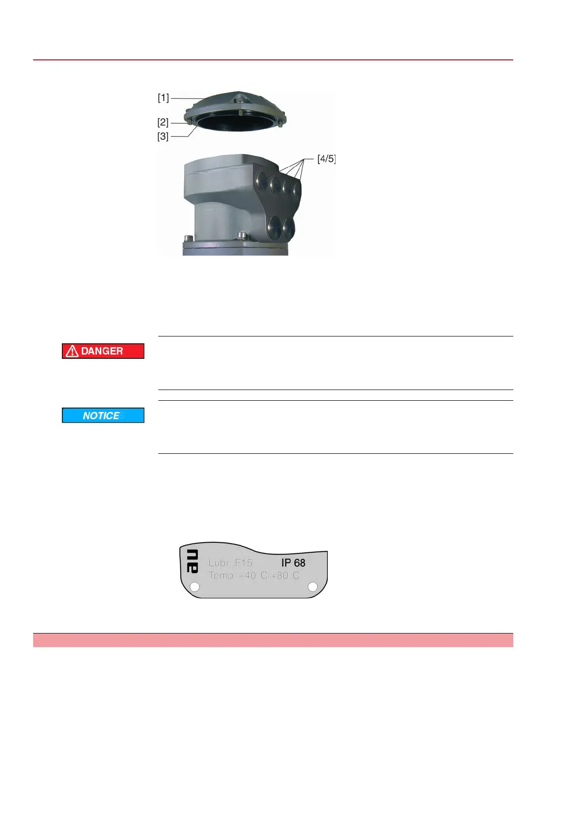
Figure 14: AUMA plug/socket connector SD bus
[1] Cover (bus terminal compartment)
[2] Screws for cover
[3] O-ring
[4] Cable entries for bus cables
[5] Blanking plug
Hazardous voltage!
Risk of electric shock.
→
Disconnect device from the mains before opening.
Electrostatic discharge ESD!
Risk of damage to electronic components.
→
Earth both operators and devices.
1. Loosen screws [2] and remove cover [1].
2. Insert cable glands suitable for bus cables.
➥
The enclosure protection IP… stated on the name plate is only ensured if suita-
ble cable glands are used.
➥
Example: Name plate shows enclosure protection IP 68.
3. Seal unused cable entries [4] with suitable blanking plugs [5].
4. Insert the wires into the cable glands.
5.2.5 Bus cables: connect
Versions
The bus connection described in this chapter applies to the following versions of the
connection board:
●
Standard version (1-channel)
●
Versions with overvoltage protection (up to 4 kV)
●
Versions for redundancy (2-channel)
Information For loop redundancy, automatic termination is performed as soon as the AUMATIC
is connected to the power supply. When interrupting the power supply, e.g. after re-
moving the AUMA plug/socket connector, both RS-485 loop segments are automa-
tically connected to each other.
20
SG 05.1 – SG 12.1/SGR 05.1 – SGR 12.1 Control unit: electronic (MWG)
Electrical connection AC 01.1 Non-Intrusive Modbus RTU

 Loading...


