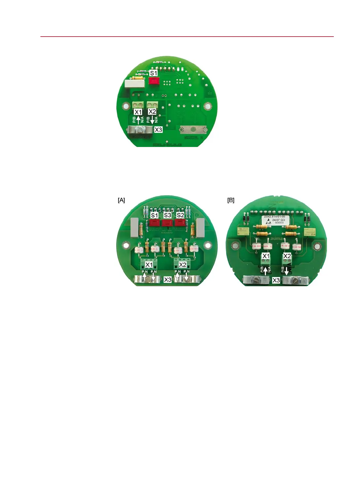
Figure 16: Connection board (standard version)
[S1] Bus termination channel 1
[X1]
Channel 1, ↑ from the previous device
[X2]
Channel 1, ↓ to the next device
[X3] Shielding clamp
Figure 17: Connection boards (versions with overvoltage protection)
[A] Board for line topology
[B] Board for loop topology (loop redundancy)
[S1] Bus termination channel 1
[S2] Bus termination channel 2
[S3] Redundancy
[X1]
Channel 1: ↑ from the previous device ↓ to the next device
[X2]
Channel 2: ↑ from the previous device ↓ to the next device
[X3] Shielding clamps
21
SG 05.1 – SG 12.1/SGR 05.1 – SGR 12.1 Control unit: electronic (MWG)
AC 01.1 Non-Intrusive Modbus RTU Electrical connection

 Loading...


