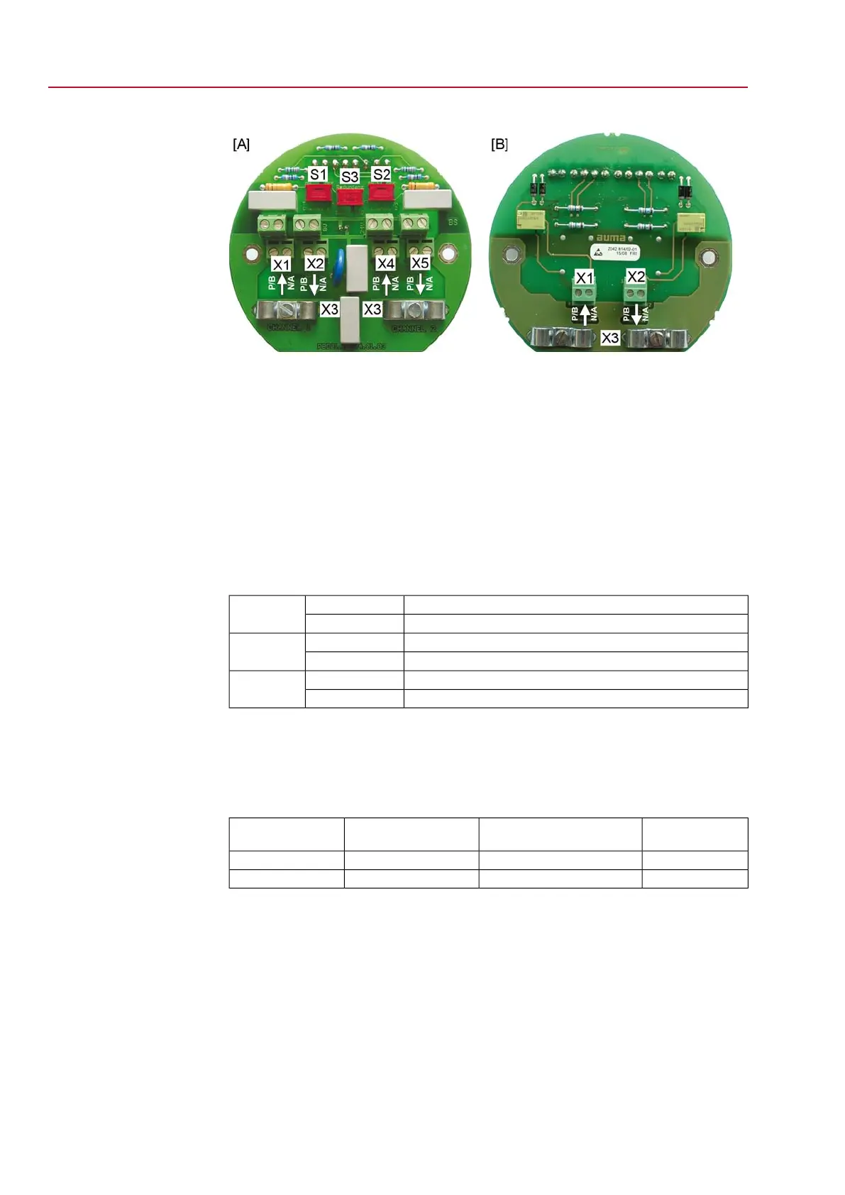
Figure 18: Connection baords (versions for redundancy)
[A] Board for line topology
[B] Board for loop topology (loop redundancy)
[S1] Bus termination channel 1
[S2] Bus termination channel 2
[S3] Redundancy
[X1]
Channel 1: ↑ from the previous device
[X2]
Channel 1: ↓ to the next device
[X3] Shielding clamps
[X4]
Channel 2: ↑ from the previous device
[X5]
Channel 2: ↓ to the next device
Table 5: Functions for switches S1 – S3
Bus termination channel 1 ONONS1
Bus termination channel 1 OFFOFF
Bus termination channel 2 ON (option)ONS2
Bus termination channel 2 OFF (option)OFF
one fieldbus board1SPCS3
two fieldbus boards (redundancy, option)2SPC
Information Switches S1 and S2 are supplied in OFF position.
Connecting bus cables:
1. Connect cables.
Table 6: Assignment of fieldbus cables
ColourSUB-D 9 plug pin (for other
fieldbus devices)
AUMA labelling at the
connection
Fieldbus cables
green8N/AA
red3P/BB
2. If the actuator is the final device in the bus segment:
2.1 Switching on the termination resistor for channel 1 using switch S1 (ON
position).
2.2 For component redundancy: Switching on the termination resistor for
channel 2 using switch S2 (ON position). Refer to table <Functions for
switches S1 – S3>.
Information: As soon as the termination resistors are switched on, the
connection to the next Fieldbus device is automatically interrupted to avoid
multiple terminations (not applicable for overvoltage protection).
3. Connect cable shield largely to shielding clamp [X3].
22
SG 05.1 – SG 12.1/SGR 05.1 – SGR 12.1 Control unit: electronic (MWG)
Electrical connection AC 01.1 Non-Intrusive Modbus RTU

 Loading...


