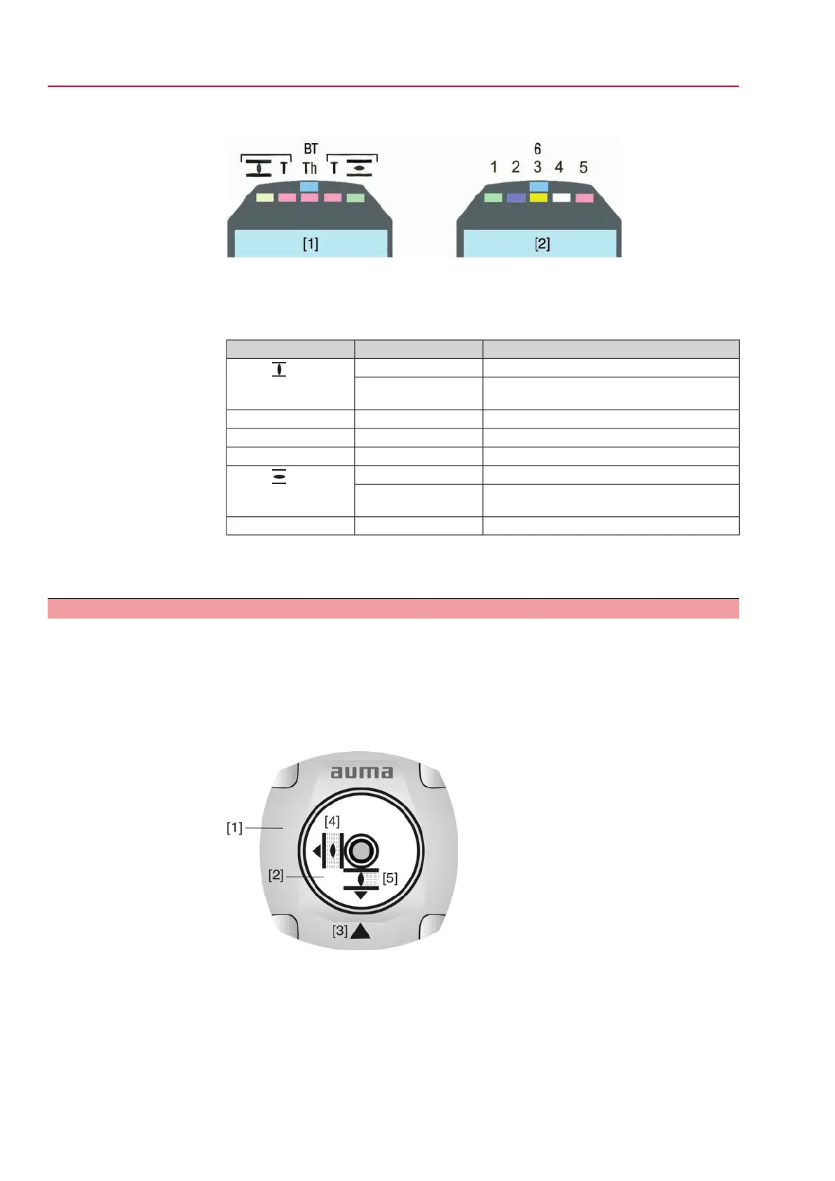
Figure 32: Indication lights/LEDs on local controls
[1] Marking with symbols (standard)
[2] Marking with figures (option)
Table 7: Meaning of signals
Meaning of signalBehaviour (default)Indication light
Actuator is in end position CLOSEDilluminated
LED 1 ( )
Running indication: Actuator runs in direction
CLOSE
blinking
Torque fault CLOSEilluminatedLED 2 (T)
Motor protection trippedilluminatedLED 3 (Th)
Torque fault OPENilluminatedLED 4 (T)
Actuator is in end position OPENilluminated
LED 5 ( )
Running indication: Actuator runs in direction
OPEN
blinking
Bluetooth connection availableilluminatedLED 6 (BT) (option)
Information
The behaviour (blinking/illuminated) can be changed via the BLINKER (M1311)
parameter.
7.3 Mechanical position indicator/running indication
Mechanical position indicator:
●
Continuously indicates the valve position
(For a swing angle of 90°, the indicator disc [2] rotates by approximately 180°.)
●
Indicates whether the actuator is running (running indication)
●
Indicates that the end positions are reached (via indicator mark [3])
Figure 33: Mechanical position indicator
[1] Cover
[2] Indicator disc
[3] Mark
[4] Symbol for position OPEN
[5] Symbol for position CLOSED
34
SG 05.1 – SG 12.1/SGR 05.1 – SGR 12.1 Control unit: electronic (MWG)
Indications AC 01.1 Non-Intrusive Modbus RTU

 Loading...


