Home
Austro Engine
Engine
IAE50R-AA
Austro Engine IAE50R-AA User Manual
4
of 1
of 1 rating
87 pages
Give review
Manual
Specs
To Next Page
To Next Page
To Previous Page
To Previous Page
Loading...
ENGINE MANUAL
IAE50R
–
AA
E1.01
.0
5
–
E
Issue date:
25
.Jan.2018
Page:
19
-
13
Revision no: 9
19.3
Sensors and actuators
19.3.1
Air Temperature sens
or
The sensor should be instal
led with its probe in t
he induction airflow.
Type of Air Temp Sen
sor(s):
Part Number
QTY per engine
E4A-
40
-000
-804
1
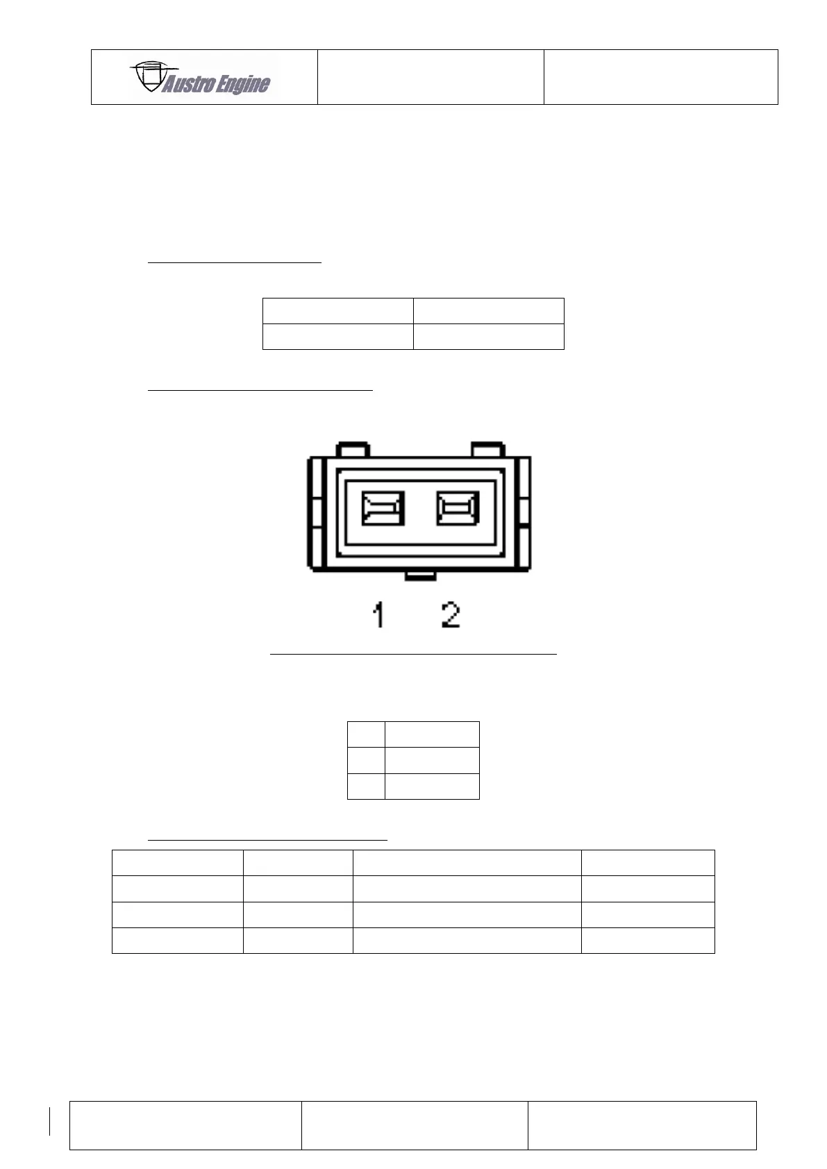
Pin Assignment Air Temp
Sensor(s):
Fig.
19
Pin
Description
1
GND
2
Signal
Mating Connector for Air
Temp Sensor:
Description
Manufacturer
Part Number
QTY (per sensor)
Seal
Bosch
1 987 280 106 / 1 987
280 107
2
Crimp
Bosch
1 987 280 103 / 1987
280 105
2
Connector Housing
Bosch
1 237 000 036
1
72
74
Table of Contents
Default Chapter
2
Issue Date: 25.Jan.2018 Revision
2
Table of Contents
4
1 Introduction
8
Record of Revisions
9
List of Revisions
10
List of Valid Pages
12
List of Incorporated Temporary Revisions
14
2 General Information
15
3 Safety Information
16
Safety Symbols
16
Model Designation Breakdown
17
Replacement Parts
17
4 Reserved
18
5 General Engine Data
19
Description
19
Technical Data
19
Design Responsibility
19
Certification
19
Engine Overall Dimensions
20
Engine Particulars
21
Out - Put Drive
21
Net Dry Weight
21
Cooling
22
Fuel Specification
22
Fuel Consumption Curve
22
Pressure to Fuel Injector
23
Lubrication
23
Oil Specification
23
6 Operating Data / Limitations
24
Maximum Take - off Rating
24
Maximum Continuous Rating
24
Power Curve
25
Operating Limitations
25
Engine RPM
25
Ambient Temperature Limits
25
Liquid Coolant Temperature Limits
26
Rotor Cooling Air Outlet Temperature Limits
26
Exhaust Gas Temperature (EGT)
26
Fuel Pressure
26
Altitude
26
Manuals
26
7 Components
27
Description of Components
28
Rear Assemblies
28
Front Assemblies
28
Centre and Rotating Assembly
28
Rotor Sealing
28
8 Descriptions of Systems
29
Fuel System
29
Typical Schematic Fuel System (Provided by Engine Installer)
29
Throttle Valve Setting
29
Cooling System
30
Liquid Cooling System
30
Water Pump
30
Temperature Regulation
30
Coolant
31
System Pressure
31
Air Cooling System
31
Rotor Cooling Air Parts
32
9 Operating the Engine
33
Starting Procedure and Warm-Up
33
Engine Start down to Approximately -10 °C
34
Ground Tests
34
Full Power Check
34
Idle Check
35
Stopping the Engine
35
Power Loss at Altitude
35
Storage
36
Storage up to 90 Days
36
Storage Beyond 90 Days
36
Returning to Service from Storage
37
10 Engine Emergency Procedures
38
Fan Belt Failure
38
Low Oil in the Tank
38
Low Fuel Pressure
38
Rotor Cooling Air Temperature
38
Coolant Temperature
38
11 Maintenance Notes
39
Austro Engine Gmbh Available Consumables
39
General Torque Settings
39
Specific Torque Settings
39
MAP Hoses
40
Checking & Setting Fan Belt Tension
40
Adjusting Engine Idle Speed
40
12 Scheduled Maintenance
41
Maintenance Schedule
41
Typical 50 Hours Check
42
Mandatory Life Limitation
43
13 Cooling System
44
Liquid Cooling System
44
Coolant Leak Check
44
Coolant System Filling and Bleeding
44
Coolant System Pressure Test
45
Air Cooling System
46
Fan Belt
46
Fan Belt Replacement
46
Air Filters
47
Air Filter Cleaning Procedure
47
Rotor Cooling Air Fan Impeller
48
14 Engine Internal Inspection
49
Spark Plug
49
15 Ground Run
51
Pre-Start Checks Outside Aircraft
51
Pre-Start Checks Inside Aircraft
51
Ground Run Check List (Example)
52
16 Maintenance and Overhaul
53
17 Trouble Shooting
54
General
54
Rough Idle
54
Engine Misfires on One Spark Plug
55
Engine Cannot Develop Full Power
55
Excessive Rotor Cooling Outlet Temperatures
55
Liquid Coolant Overheats on Medium and High Power
55
ECU Error Warning Light Flashes
56
18 Notes for Installers of Engines
57
General Notes
57
Notes for Engine Installers
57
Fuel System
58
Fuel Specification
58
Fuel Delivery
58
Fuel Filters
59
Pressure Regulator
59
Water in Fuel
59
Fuel Lines
59
Oil System
59
Engine Mounting
60
Exhaust System
60
Air Filters
60
Drive Interface
60
19 Electrical System
61
Engine Control System
62
Fuel Injection
62
19.1.1.1 Injection Timing
62
19.1.1.2 Load Demand
62
Ignition System
62
19.1.2.1 Ignition Triggering
62
19.1.2.2 Ignition
62
Mechanical Installation of the ECU
63
Electrical Installation of the ECU
64
19.1.4.1 Harness Connector for ECU
65
19.1.4.2 ECU Pin Assignment
66
19.1.4.3 CAN Bus
68
19.1.4.4 Option: Installation of ECU According D0160 Section 16 CAT Z
69
19.1.4.5 Error Codes
70
19.1.4.6 Error Code Table
71
GND Concept IAE50R
72
Sensors and Actuators
73
Air Temperature Sensor
73
Rotor Cooling Air out Temperature Sensor
74
Map Sensors
76
Speed Sensors
77
Ignition Coils
78
19.3.5.1 H.T. Leads
79
Spark Plugs
79
Injector
80
Coolant Temperature Sensor for Instruments
81
Generator Regulator and Generator Wiring
82
Mechanical Installation of the Generator Regulator
82
Electrical Installation of the Regulator
83
Starter
84
Mechanical Installation
84
Electrical Connection of Starter
84
Electronic Components Capability
85
Electrical Tests
85
Environmental Tests
86
Control System Reliability
87
Control System Reliability Objective
87
19.6.3.2 Software Quality Level
87
4
Based on 1 rating
Ask a question
Give review
Questions and Answers:
Need help?
Do you have a question about the Austro Engine IAE50R-AA and is the answer not in the manual?
Ask a question
Austro Engine IAE50R-AA Specifications
General
Brand
Austro Engine
Model
IAE50R-AA
Category
Engine
Language
English
Related product manuals
Austro Engine AE50R
68 pages
Austro Engine E4P
56 pages
Austro Engine AE300
360 pages