ENGINE MANUAL
IAE50R – AA
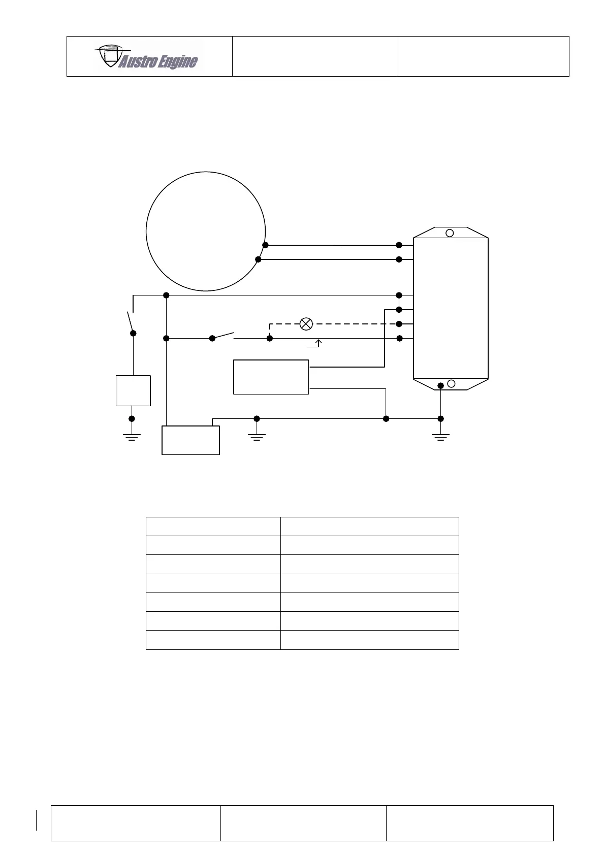
19.4.2 Electrical installation of the Regulator
The wiring for connecting the generator and generator regulator is described in following
figure:
GEN
BATT
12V
yellow
yellow
white
red
red
black
12V -3W
Not requsted
22000 µF
40-65V
+
-
> AWG 14
AWG 16
AWG 16
AWG 16
AWG 16
AWG 16
AWG 16
No Load on Black Terminal
Load
+ -
Regulator
Fig. 28: Wiring diagram Generator and Regulator
Power (+12V) Switchable (ON / OFF)
10.1.2 Charge Circuit Fail Alarm
The installer is responsible for a wiring which indicate a charge circuit failure alarm. In the
unlikely event of a charging circuit failure, indicated by the appropriate alarm, the electrical
bus bar will be fed automatically from the battery. Any non–essential electrical items should
be switched off.
The battery should be capable of providing sufficient power to run the ECU unit etc. for a
minimum of ½ hour. Reducing power will not significantly increase engine–running time.