9
3 Connect the transformer wires to the Com and 24 Vac screw terminals.
24 Vac
Com
Run LED
Power LED
9
8
7
6
5
4
3
2
1
0
9
8
7
6
5
4
3
2
1
0
1 2 3 4 5 6 7 8
O
N
4 Apply power to the Room Controller.
5 Measure the voltage at the Room Controller’s power input terminals to verify that the
voltage is within the operating range of 21.6–26.4 Vac.
6 Plug the terminal connector into the back of the Room Controller.
7 Verify that the Power LED is on and the Run LED is blinking.
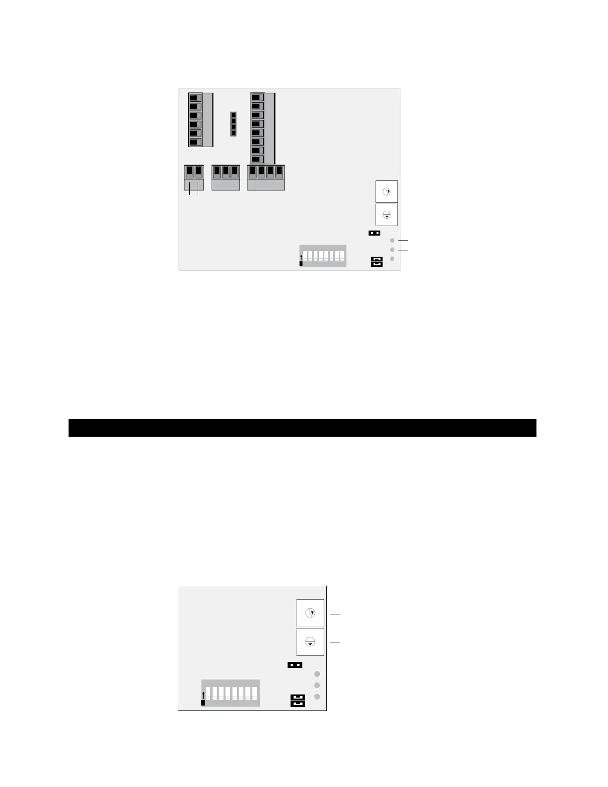
You must give the Room Controller an address that is unique on the network. You can
address the Room Controller before or after you wire it for power.
1 If wired for power, remove power from the Room Controller. The Room Controller
reads the address each time you turn it on.
2 Using the rotary switches, set the address to match the Address in the Room
Controller's
Device Properties dialog box in SiteBuilder. Set the 10's switch to the tens
digit of the address, and set the
1's switch to the ones digit.
EXAMPLE If the address is 25, point the arrow on the 10's switch to 2 and the arrow
on the
1's switch to 5.
10’s
1’s
9
8
7
6
5
4
3
2
1
0
9
8
7
6
5
4
3
2
1
0
1 2 3 4 5 6 7 8
O
N
To address the Room Controller
 Loading...