30
• Acceptable voltage drop in the wire from the controller to the controlled device
• Resistance (Ohms) of the chosen wire gauge
• Maximum current (Amps) the controlled device requires to operate
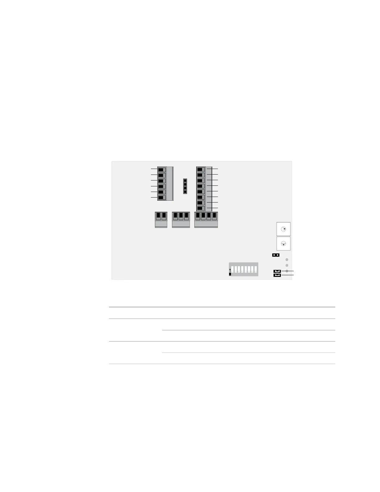
1 Verify that the Room Controller's power and communications connections work
properly.
2 Remove power from the Room Controller.
3 Connect input and output wiring to the Room Controller’s screw terminals. See the
control program's point list in Appendix B (page 42) to determine which input and
output numbers to use.
Analog Output 1
Analog Output 2
Digital Output 1
Digital Output 2
Digital Output 3
Digital Output 4
Digital Output 5
Digital Output 6
Input 1
Input 2
Input 3
Input 4
Ground
Ground
UI-3 Jumper
UI-4 Jumper
9
8
7
6
5
4
3
2
1
0
9
8
7
6
5
4
3
2
1
0
1 2 3 4 5 6 7 8
O
N
4 Set the UI-3 and UI-4 jumpers.
Input 3
Dry contact Put on
0-5 Vdc Remove
Input 4
Dry contact Put on
0-5 Vdc Remove
5 Apply power to the Room Controller.
To wire inputs
and outputs