13
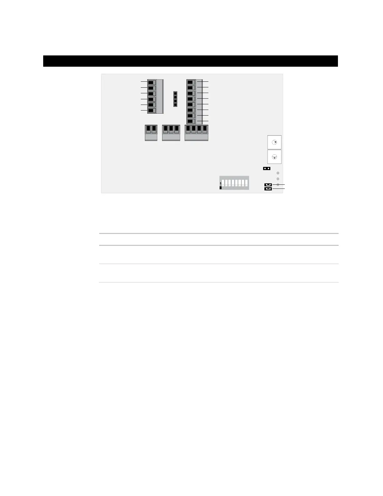
Analog Output 1
Analog Output 2
Digital Output 1
Digital Output 2
Digital Output 3
Digital Output 4
Digital Output 5
Digital Output 6
Input 1
Input 2
Input 3
Input 4
Ground
Ground
UI-3 Jumper
UI-4 Jumper
9
8
7
6
5
4
3
2
1
0
9
8
7
6
5
4
3
2
1
0
1 2 3 4 5 6 7 8
O
N
Input wiring
Thermistor
Dry contact
1000 feet
(305 meters)
22 AWG Shielded
0–5 Vdc 1000 feet
(305 meters)
26 AWG Shielded
Output wiring
To size output wiring, consider the following:
• Total loop distance from the power supply to the controller, and then to the controlled
device
NOTE Include the total distance of actual wire. For 2-conductor wires, this is twice the
cable length.
• Acceptable voltage drop in the wire from the controller to the controlled device
• Resistance (Ohms) of the chosen wire gauge
• Maximum current (Amps) the controlled device requires to operate
1 Verify that the Room Controller's power and communications connections work
properly.
2 Remove power from the Room Controller.
3 Connect the input wiring to the screw terminals on the Room Controller.
Wiring inputs and outputs
Wiring
specifications
To wire inputs
and outputs
 Loading...