83
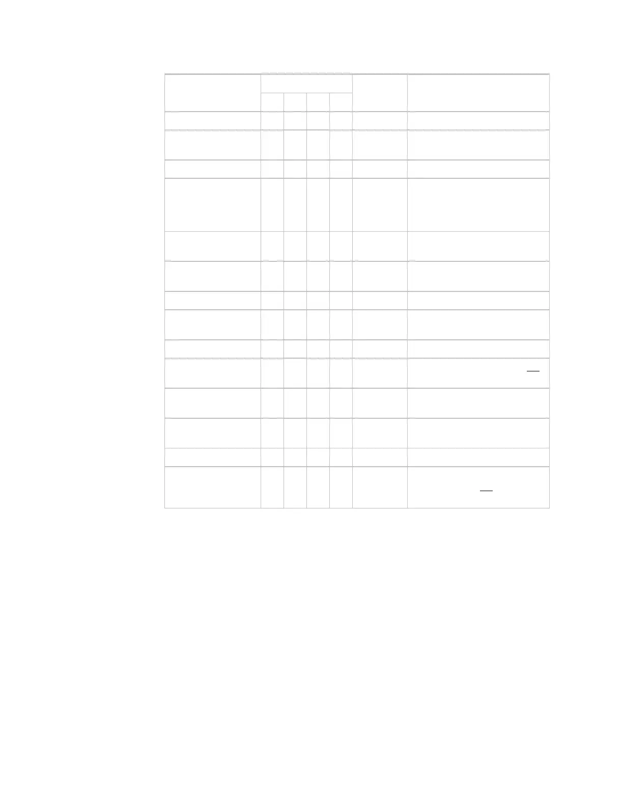
Zone temp X
Internal
Zone setpoint
adjust
X
Internal
Zone override
X
Internal
Outdoor air temp X
UI-1 Optional – Requires sensor
(Type II thermistor)
Short input to ground if
not used.
Discharge air temp X
UI-2 Optional – Requires sensor
(Type II thermistor)
Freezestat
X
UI-3 Optional – Requires sensor
(dry contact)
Cooling stage 1
X
DO-1 (Y1) Relay output
Cooling stage 2
X
DO-2 (Y2) Optional – Use this output if 2-
stage cooling is present
Fan start/stop
X
DO-3 (G) Relay output
Heating stage 1
X
DO-4 (W1) Optional – Use this output OR
Heating stage 2
hot water valve
X
DO-5 (W2) Optional – Use this output if 2-
stage heating is present
Fan second speed
X
DO-6 Connect this output to DO-3 if
using a single-speed fan
Mixed air dampers
X AO-1 0–10 Vdc
Hot water valve
X AO-2 Optional – 0–10 Vdc
Use this output
OR
staged
heating
Run conditions - scheduled
User-defined schedules determine when the unit runs in:
• Occupied Mode
The unit maintains a 74°F (23.5°C) adjustable cooling setpoint and a 70°F (21°C)
adjustable heating setpoint.
• Unoccupied Mode (night setback)
The unit maintains an 85°F (29.5°C) adjustable cooling setpoint and a 55°F (13°C)
adjustable heating setpoint.
Zone setpoint adjust
The occupant can adjust the heating and cooling setpoints at the zone sensor.
Point list
Sequence of
operation



 To Next Page