29
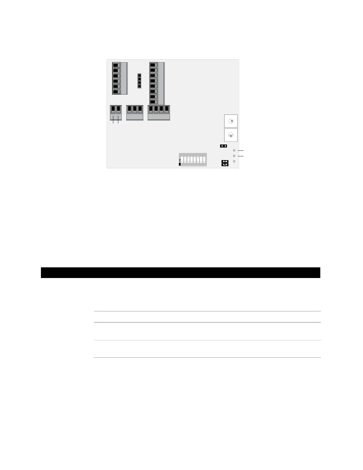
3 Connect the transformer wires to the Com and 24 Vac screw terminals.
24 Vac
Com
Run LED
Power LED
9
8
7
6
5
4
3
2
1
0
9
8
7
6
5
4
3
2
1
0
1 2 3 4 5 6 7 8
O
N
4 Apply power to the Room Controller.
5 Measure the voltage at the Room Controller’s power input terminals to verify that the
voltage is within the operating range of 21.6–26.4 Vac.
6 Plug the terminal connector into the back of the Room Controller.
7 Verify that the Power LED is on and the Run LED is blinking.
Input wiring
Thermistor
Dry contact
1000 feet
(305 meters)
22 AWG Shielded
0–5 Vdc 1000 feet
(305 meters)
26 AWG Shielded
Output wiring
To size output wiring, consider the following:
• Total loop distance from the power supply to the controller, and then to the controlled
device
NOTE Include the total distance of actual wire. For 2-conductor wires, this is twice the
cable length.
Wiring inputs and outputs
Wiring
specifications
 Loading...