28
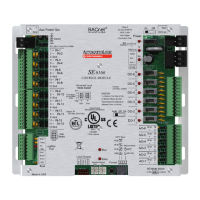
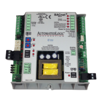
You can install the RC642D Room Controller as a stand-alone unit, but not the RC642.
NOTE If needed, the Room Controller has a secondary backplate that you can mount
behind it to cover certain junction boxes.
1 Pull the backplate off the Room Controller. If necessary, turn the setscrew in the
bottom of the Room Controller clockwise until you can remove the backplate.
2 Pull the power and input/output wiring through the rectangular opening in the
backplate (and the secondary backplate if you are using it).
3 Use screws to mount the backplate to a junction box. The holes in the backplate
accommodate most standard junction boxes.
4 After you connect the power (page 8) and input/output (page 13) wiring to the Room
Controller and select a control program (page 31), attach the cover and circuit board
to the mounted backplate.
5 Turn the setscrew one full turn counterclockwise so that the cover cannot be
removed.
CAUTIONS
• The Room Controller is powered by a Class 2 power source. Take appropriate
isolation measures when mounting it in a control panel where non-Class 2 circuits are
present.
• ALC controllers can share a power supply as long as you:
○ Maintain the same polarity.
○ Use the power supply only for ALC controllers.
1 Remove power from the Room Controller.
2 Unplug the Comm/24 Vac screw terminal connector from the back of the Room
Controller.
METHOD B: Installing a stand-alone Room Controller
To mount the Room Controller
To wire for power