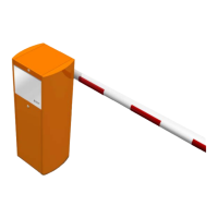
The BL 229 is an automatic rising barrier designed for vehicle access control, with two main models: the "BL 229" (standard) and the "BL 229 Toll" for motorway applications.
Function Description:
The barrier controls vehicle access by raising and lowering a boom arm. Its movement is managed by a gear motor, assisted by one or two balancing springs, ensuring minimal effort during both opening and closing. The speed of the arm's movement is adjustable, controlled by a frequency converter, and configured at the factory for progressive accelerations and controlled decelerations. An analog sensor continuously monitors the arm's exact position, allowing for precise control and adjustments, such as increasing motor torque in windy conditions. The barrier can be operated via various inputs including key switches, push-buttons, radio transmitters, detection loops, or external units. In the event of a power failure, the barrier is factory-configured to remain locked, but this can be modified to allow the boom arm to automatically rise to an equilibrium position (around 45°) for manual opening. The BL 229 Toll model and the optional BL 229 Standard model include a swing-off device for the boom arm, which allows the arm to detach upon impact, preventing damage to the barrier and the hitting vehicle. The control board (AS1620) coordinates all barrier activities, manages options, inputs, and outputs, and records operational history and potential defects.
Important Technical Specifications:
Common Technical Characteristics:
- Housing: Folded and welded sheet steel, protected from corrosion by two coats of paint.
- Internal Machine Elements: Treated against corrosion by electrogalvanization.
- Power Supply: Single phase 230VAC, 50/60Hz + Ground (not to be connected to a floating network or high impedance earthed industrial distribution network).
- Nominal Power Consumption: 335 W (at maximum speed, without option).
- Motor: Three-phase asynchronous motor of 250 W.
- Gear Motor: Worm gear motor (1:19 ratio), life-lubricated.
- Secondary Transmission: Crankshaft-connecting rod device ensuring perfect mechanical locking in extreme open and closed positions.
- Automatic Unlocking: Programmable in case of power failure, allowing manual arm push-up.
- Frequency Converter: Ensures progressive accelerations and controlled decelerations, vibration-free movement, and enhanced mechanism protection.
- Position Sensor: Inductive analog position sensor for permanent boom position monitoring.
- Balancing: Arm balanced by adjustable springs.
- Operating Temperature: -20 to +50°C (without optional heating).
- Relative Humidity: < 95%, without condensation.
- Wind Resistance: Operation unperturbed by winds of 120 km/h.
- MCBF (Mean Cycles Between Failures): 10,000,000, with normal maintenance.
- Net Weight (excluding boom arm): 83 kg.
- IP Rating: IP 44.
- Noise Emission: < 70 dB(A) (measured at 1m from surface, 1.60m above ground, according to ISO 3744).
- Compliance: Conforms to European standards CE.
Specific Technical Features:
- BL 229 (Standard):
- Aluminium Boom Profile: Round, Ø84.
- Opening/Closing Time: Adjustable between 1.2 and 4 seconds, with 3 profiles: Standard (impact force according to EN 12453), Intermediate (impact force according to EN 12453 with foam protection), and Maximum (installer must ensure compliance, e.g., with dead man operation).
- Free Passage (L): From 2 to 6 meters.
- BL 229 Toll:
- Aluminium Boom Profile: Oval, section 80 x 53 mm.
- Opening/Closing Time: From 0.6 to 1.7 seconds.
- Free Passage (L): From 2.5 to 4 meters.
Usage Features:
- Installation Flexibility: The barrier can be configured in four different ways based on the arm's position relative to the door and the road. The mechanism can be adapted for these configurations, which may require replacing the end stop unit and the front aluminum panel.
- Adjustable Arm Balancing: The tension of the balancing spring(s) must be adjusted to ensure minimal effort for the motor during both opening and closing. This involves withdrawing a screw, disconnecting the connecting rod, and then adjusting the spring tension until the arm remains balanced at various angles.
- Arm Levelling: The boom arm's horizontality can be adjusted by turning the connecting rod and then tightening the nuts, using a spirit level for accuracy.
- Analog Sensor Calibration: The analog sensor, which detects the arm's extreme positions, needs calibration, especially if the barrier's configuration is changed. This procedure involves placing the arm in the closed position, disconnecting the frequency converter, adjusting the sensor's distance from the cam, and then performing a calibration test via the maintenance interface or the integrated HMI.
- Frequency Converter Configuration: The frequency converter, a Schneider Altivar ATV12, is configured via Modbus. Only the Modbus address and baud rate are manually entered.
- Manual Opening: In case of power failure, the barrier can be manually opened using a release lever after opening the access door and switching off the main circuit breaker. The balancing spring then assists the opening movement.
Maintenance Features:
- Regular Checks: Every 6 to 12 months, depending on traffic level, a maintenance check is required. This includes verifying all adjustments (as described in Chapter 7), ensuring all nuts and screws of the mechanical unit are tight, checking electrical connections, testing the arm's ability to be stopped by hand during movement (and re-adjusting balance if necessary), and cleaning the interior and exterior of the housing.
- Lubrication: Rod ends should be lubricated with anti-corrosive multifunction grease, and bearings should be lubricated while checking the wear state of pivots and balancing spring rings.
- Filter Replacement: If equipped with a ventilation kit, the filter needs regular replacement.
- Prolonged Stoppage/Destruction: For long periods of disuse, the barrier should be stored in a dry, protected place and left turned on to prevent condensation and oil solidification in the gear motor. When decommissioning, the oil must be emptied from the gear motor, and components scrapped according to local legislation.
- Preventive Maintenance: To achieve a 10,000,000 cycles MTBF, a preventive maintenance program is recommended every 2,500,000 cycles, involving replacing rod ends, noting and replacing the balancing spring, and adjusting its tension.
- Troubleshooting: If the barrier malfunctions, troubleshooting involves checking HMI messages, reviewing installation and adjustment procedures, verifying the circuit breaker and voltage, checking motor and frequency converter status (red LED blinking indicates fault), inspecting command connections, and performing electrical opening/closing tests. After prolonged power-off, several opening/closing cycles may be needed to warm up the gear motor and ensure correct unlocking and balancing.