6.5. INSTALLATION OF THE TIP SUPPORT
BL 229: available in option.
BL 229 Toll: unavailable.
The tip support is automatically provided with any barrier of more than 5m and is optionally available for shorter boom arms.
The tip support’s role is to maintain the end of the boom arm in its horizontal position and to ensure its rigidity.
The tip support must be fixed on a concrete base, according to the instructions of drawing CH2656 ( Chap. 11, page 47).
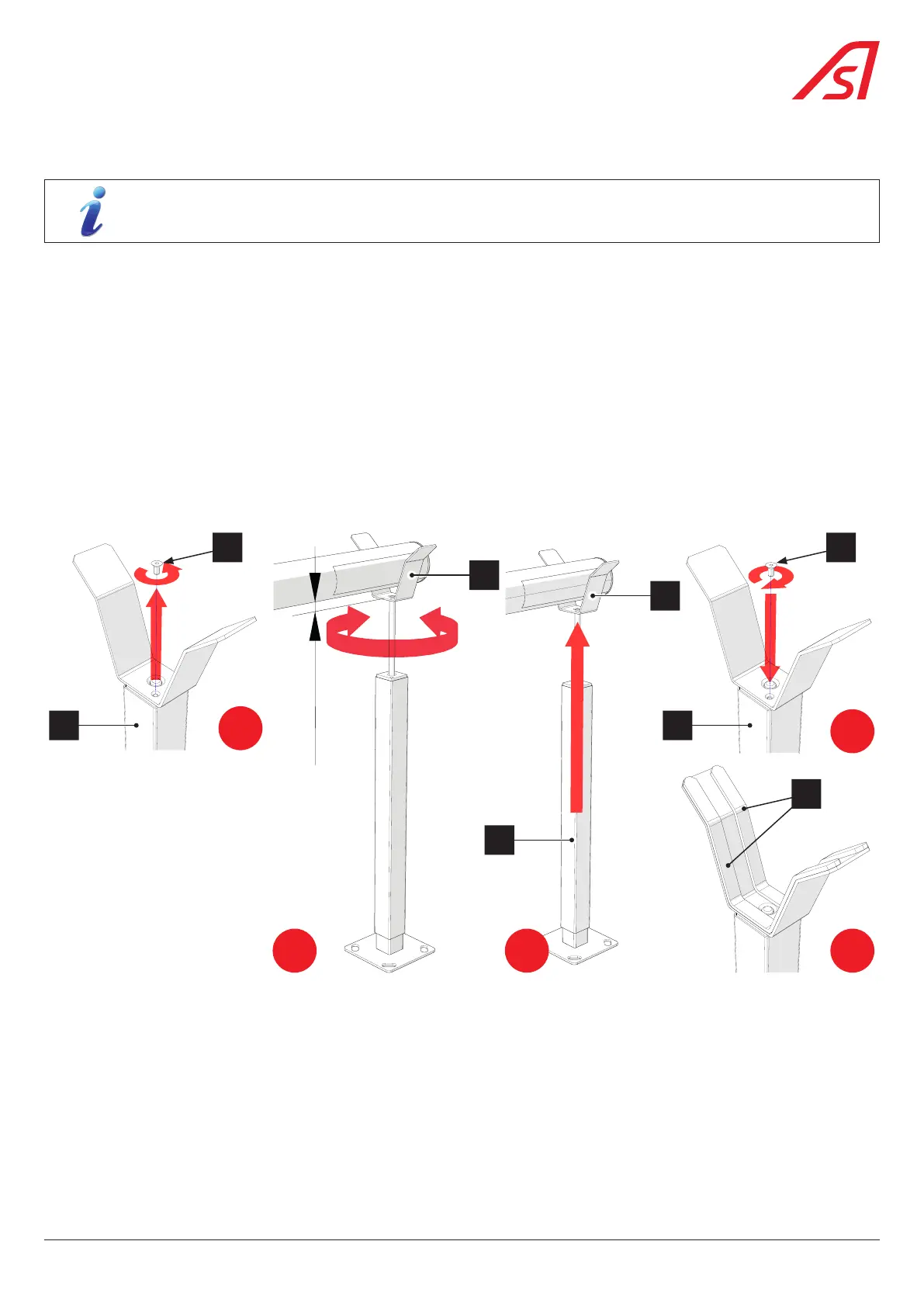
The height of the tip support is to be adjusted once the boom arm has been levelled ( Chap. 7.5, page 32):
• Remove screw (1) while holding upper element (3).
• Turn fork (2) in the necessary direction so that the end of the arm comes to rest in closed position ±3 cm above the tip
support.
• Push the upper part (3) back under the fork (2) and tighten screw (1), previously withdraw.
• Then place the foam strips (4) that will be used to cushion the impact between the beam and the lyre..
• Align the arm in the tip support by making, if necessary, the barrier swivel on its base.
• Tighten the nuts (Rep. 36, Chap. 6.2, page 16) to ensure the final fastening of the barrier..
3
1
± 30 mm
2
3
2
3
1
4
1
2 3
4
5
Fig. 21 - Installation of an adjustable tip support
25
BL 229