6.1. PREPARING THE BASE PLATE
As the barrier cannot be put directly on the ground, it will consequently be necessary to secure it, at choice:
- Either on a concrete base plate, by means of the fixing frame provided on demand (detailed procedure hereafter);
- Or on a steel platform (provided as an option);
For the positioning of the base plate, please refer to the Installation Drawings ( Chap. 11, page 47), which takes precedence
over any other information.
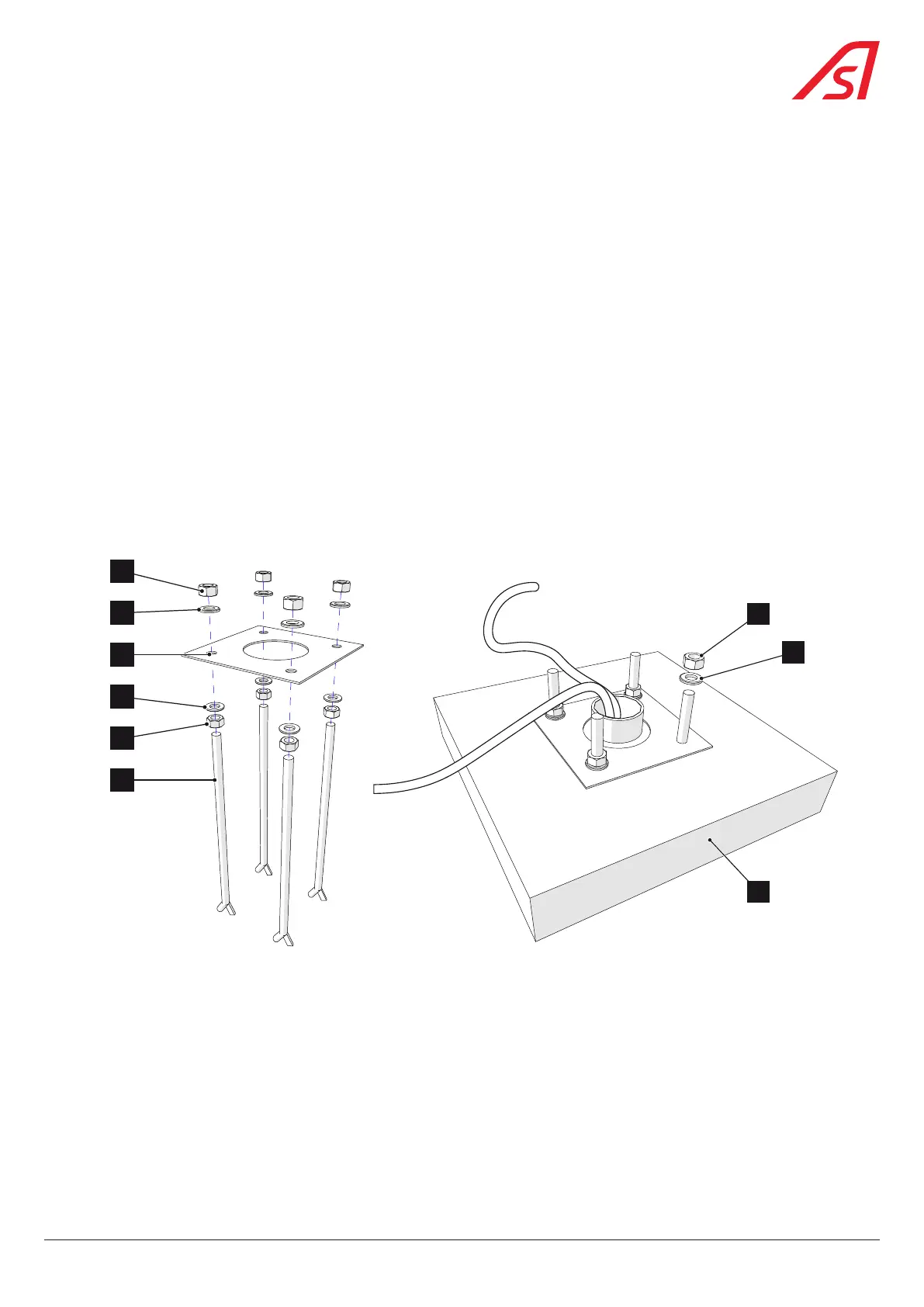
Introduce the four fixing bolts (27), each provided with a nut (32) and a flat washer (33), in the holes of the fixing frame (34).
The thread must be directed upwards as illustrated. Assemble the fixing bolts on the fixing frame by tightening a flat washer
(35) and a nut (36) on each thread and by letting the thread exceed the frame (34) by the height defined in the Installation
Drawings. Use adhesive tape to protect the threads from concrete splashes.
Fit the PVC tubes and install the power cable (to the general power board), the command cable (to the control box) and the
detection cable (to the loops and/or possible cells), leaving a tail of approximately 1 meter.
The cabling must be carried out in accordance with the standards in force in the country where the installation takes place.
Build a concrete base (37) and place the base plate in it. The frame (34) must be flush mounted with the platform and perfectly
horizontal.
When the concrete has set, remove the adhesive tape from the threads and remove the nuts (36) and the flat washers (35),
which will be used for fixing the barrier.
36
34
27
35
33
32
36
35
37
Fig. 5 - Preparing the base plate
15
BL 229