7.6. ANALOG SENSOR SETTINGS
The analog sensor and cam are usually installed in factory according to the customer requested solution and will require no
manipulation.
However, if the solution is changed in the field, make sure your cam and analog sensor are mounted appropriately for the new
solution.
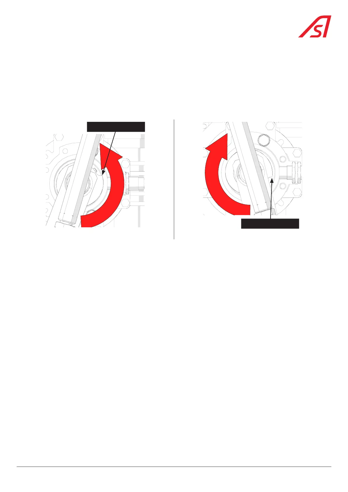
The illustration below shows the front view of the motor when the side access panel is open. It shows the correct cam and
analog sensor position according to the possible solutions ( Ch. 6.3, page 18)
Cam edge
Cam edge
Fig. 29 - Analog sensor - Solution 1 & 2 Fig. 30 - Analog sensor - Solution 3 & 4
Should you need to change the analog sensor and cam position in the field proceed as described below.
Please, refer to the illustrations above and below.
1. Open the door and turn OFF the power;
2. Thanks to the unlocking lever, unlock the mechanism and place the gate arm in open position ( Fig. 32, page 34);
3. Remove the arm (proceed in the reverse order of the Chap. 6.4, page 21);
4. Loosen the spring(s) and remove it (them);
5. Remove the stops assembly;
6. Disconnect the connecting rod from the gear motor shaft by unscrewing the screw (1) ( Fig. 31, page 34);
7. Unscrew the screw (2) and remove the gear motor shaft ( Fig. 33, page 34);
8. Loosen the two pressure screws (3) of the spiral cam ( Fig. 34, page 34);
9. Return the spiral cam and replace it correctly (the cam edge must be close to the analog sensor when the arm is in closed
position) onto the gear shaft, tighten the two pressure screws (3);
10. Reinstall the gear motor shaft on the gear motor and secure it with the screw (2);
11. Reattach the connecting rod to the gear motor shaft by reattaching the screw (1);
12. Reinstall the stops assembly considering the desired solution ( Ch. 6.3, page 18);
13. Reinstall the spring in its correct position considering the desired solution and reload it ( Ch. 7.2, page 29);
14. Mount the gate arm back ( Ch. 6.4, page 21);
15. Proceed with the analog sensor calibration procedure ( Ch. 7.7, page 35).
33
BL 229