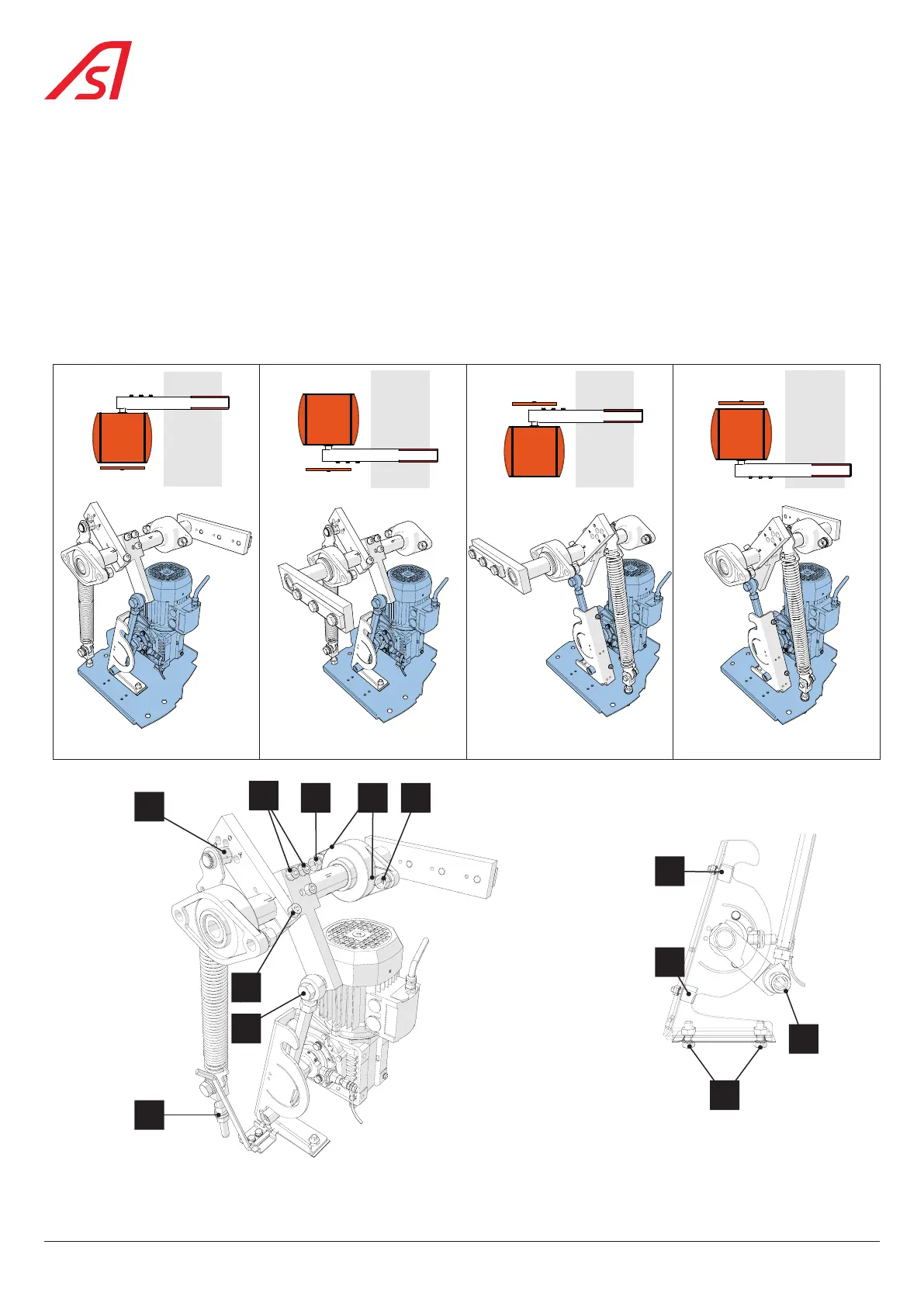
6.3. CONVERSION FROM ONE SOLUTION TO ANOTHER
The barrier can be configured in 4 different ways, according to the position of the arm with regard to the door and the road.
To move from one configuration (solution) to another, the mechanism must be adapted: the arm is either on the door side
(solution 2+3) or opposite to the door side (solution 1+4), and the motor turns in one direction (solution 1+2) or the other one
(solution 3+4).
The gear motor, the crankshaft and the connecting rod (19, 18 et 20) (shaded here below) remain fixed. On the other hand, the
end stop unit (17) used for solutions 1 and 2 is different from that of solutions 3 and 4. Similarly, the front aluminium panel (4),
will have to be replaced by a new one in most of cases.
All the other parts are interchangeable from one solution to another.
Door
Solution 1 (std)
Road
Door
Solution 2
Road
Door
Solution 3
Road
Door
Solution 4
Road
Fig. 9 - Solution 1 Fig. 10 - Solution 2 Fig. 11 - Solution 3 Fig. 12 - Solution 4
G
B
H
F
A
CD D
J
E
K
L
Fig. 13 - Changing the solution (Markers) Fig. 14 - Changing the solution (Details)
Table of operations to be carried out, marked , to move from one solution to another:
18
BL 229