7. ADJUSTMENTS
7.1. POSITIONNING THE LEVERS ON THE ARM SHAFT
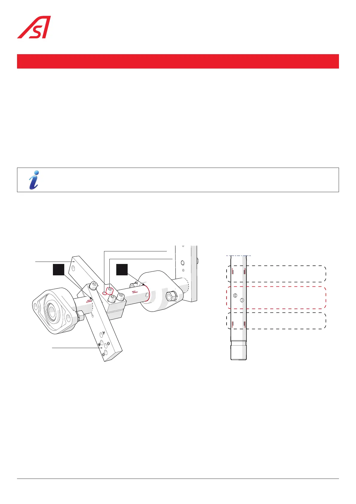
The connecting rod and spring levers ( Rep.10 and 11, Chap. 5.1, page 9) must be positioned on the arm shaft ( Rep.9,
Chap. 5.1, page 9) according to the chosen solution.
1. Screw the rod lever onto the shaft, by passing the screw through the holes in the rod and shaft corresponding to the
considered solution ( Fig. 24 and Fig. 25).
2. Align mark (C) of the spring lever with the mark on the shaft corresponding to the considered solution ( Fig. 25):
figures indicated on the illustration (1 to 4) indicate the reference mark to be used according to the considered solution (1 to 4).
For a correct alignment, the mark must remain entirely visible ( Fig. 24).
With correct positioning, the pivots (G and H, Fig. 13, page 18) maintaining the connecting rod and the spring in their
respective levers are perpendicular to it.
The screws of the rod lever must be tightened with a torque of 60 Nm, the one of the spring lever with a torque
of 80 Nm.
Similarly, the arm shaft must be positioned in relation to the bearings so that the circular reference mark on the arm shaft (D)
is level with the side of the bearing ( Fig. 24).
The bearing’s compression screws (C, Fig. 13, page 18) re then positioned in front of the groove marked in the arm shaft
for this purpose
C D
Rod lever
Holes for solutions 1 & 2
Holes for solutions 3 & 4
Spring lever
Fig. 24 - Arm shaft (Solution 4)
3
1&3
2&4
2
1
4
Reference marks for spring lever
(use the small marks (in black))
Holes for rod lever
Reference marks for spring lever
(use the small marks (in black))
Fig. 25 - Rod and spring levers marks on the shaft, according
to the considered solution
28
BL 229