In order to reach a 10.000.000 cycles MTBF, we recommend performing a preventive maintenance program every
2.500.000 cycles:
• Replace the rod ends ( Rep. 3, Chap. 7.5, page 32)
• Take note about the position of the spring on the spring lever ( Rep. 11, Fig. 2, page 9) as well as
dimension of X ( Fig. 27, page 29) and replace the balancing spring ( Rep. 12, Fig. 2, page 9) by a new
one. Adjust the tension of the new spring ( Chap. 7.2, page 29).
8.4. TROUBLESHOOTING
If the barrier does not work correctly, check the following points:
• Check the displayed messages on the HMI of the control unit.
• Review the procedures described in Chapters 6. Installation, 7. Adjustments et 8.3. Maintenance.
• Check that the circuit breaker ( Rep. 24, Fig. 1, page 9) is properly engaged and that the voltage corresponds to the
voltage required in the technical specifications ( Chap. 9, page 43).
• Check if the motor is working.
• Check if the frequency converter ( Rep. 26, Fig. 1, page 9) s in fault: the red LED on the side of the converter blinks.
In this case, contact an Automatic Systems representative.
• Check the connection of the commands according to the electrical diagram provided with the equipment.
• Check that all the electric wires are correctly tight, and tighten them if necessary.
• Carry out an electrical opening/closing test by means of the integrated HMI (Menu > Commands).
After the equipment has been switched off for a long time, it will be necessary to carry out several opening/
closing cycles to raise the temperature of the gear motor in order to allow correct unlocking of the gearmotor and
correct balancing of the boom arm.
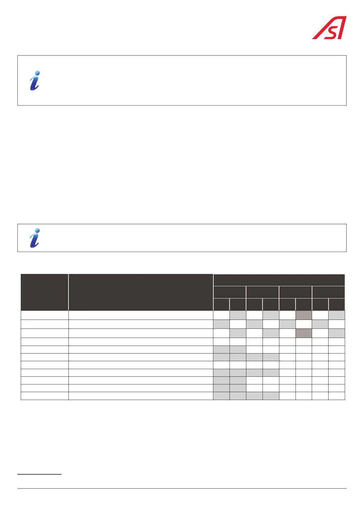
8.5. RECOMMENDED SPARE PARTS
REFERENCE DESCRIPTION
QUANTITY(IES)
2
1 BL 3 BL 5 BL 10 BL
2 TO
3 M
3,5 TO
6 M
2 TO
3 M
3,5 TO
6 M
2 TO
3 M
3,5 TO
6 M
2 TO
3 M
3,5 TO
6 M
E/7002/593
SPRING ASSEMBLY Ø 5.5 MM WITH STRETCHER (BL229 TOLL)
1 1 1 2
E/7002/826
SPRING ASSEMBLY Ø 7.0 MM WITH STRETCHER
1 1 1 2
E/7002/827
SPRING ASSEMBLY Ø 5.5 MM WITH STRETCHER
1 1 1 2
0/3551/000 RUBBER BUMPER
2 2 2 2 4 4 5 5
E/0832/031 ROD ASSEMBLY WITH STRAP
1 1 1 1 1 1
RDC-E03007 GEAR MOTOR
1 1 1 1
0/7140/284 INDUCTIVE SENSOR M18 P 8 MM S ANA 0-10V CON.M12
1 1 1 1 2 2 3 3
E/7140/474 AS1620 CONTROL BOARD ASSEMBLY (INCL. FEMALE CONNECTORS)
1 1 2 2
E/7109/777_TESTE HMI BOARD AS1621 - TESTED
1 1 1 1 1 1
0/7140/498_CONF FREQUENCY CONVERTER 230V - CONFIGURABLE
1 1 1 1 2 2
0/7108/919 POWER SUPPLY MEAN WELL 85-264VAC/24V 2,2A LRS-50-24
1 1 2 2
2 For quantities of more than 10 units, please contact our after-sales service..
41
BL 229