6.6. ELECTRICAL CONNECTIONS
DO NOT CONNECT TO A FLOATING NETWORK OR TO A HIGH-IMPEDANCE EARTHED INDUSTRIAL DISTRIBUTION NETWORK.
HIGH LEAKAGE CURRENT.
BEFORE CONNECTING THE POWER SUPPLY, IT IS ESSENTIAL TO MAKE A GROUND CONNECTION (20) USING A CABLE
WITH A MIN. CROSS SECTION OF 2.5 MM².
DO NOT CONNECT SEVERAL DEVICES ON THE SAME DIFFERENTIAL.
THE OPERATIONS MUST BE PERFORMED IN ACCORDANCE WITH THE SAFETY WARNINGS, CHAP. 1, PAGE 4.
CONNECTIONS MUST BE EXECUTED IN ACCORDANCE WITH THE WIRING DIAGRAMS (SEE ETF) INCLUDED INSIDE THE
EQUIPMENT, AS THESE REPRESENT THE PRIMARY REFERENCE INSTRUCTIONS.
IN ORDER TO AVOID INTERFERENCES, THE POWER AND CONTROL CABLES MUST PASS THROUGH TWO DIFFERENT
DUCTS AT LEAST 10CM APART.
THE ARM MUST BE MOUNTED BEFORE PROCEEDING WITH THE ELECTRICAL CONNECTIONS!
THE MAINS CABLE CANNOT BE ATTACHED TO OTHER CABLES COMING OUT OF THE HOUSING!
INSTEAD, IT MUST BE KEPT AS FAR AWAY FROM THEM AS POSSIBLE.
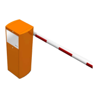
Connect the power supply cables
1
:
• Switch off the circuit breaker (19).
• Connect the neutral (blue) and the phase (brown or black)
wires of the power supply cable to the circuit breaker.
• Connect the ground wire (yellow/green) to the ground
terminal (20).
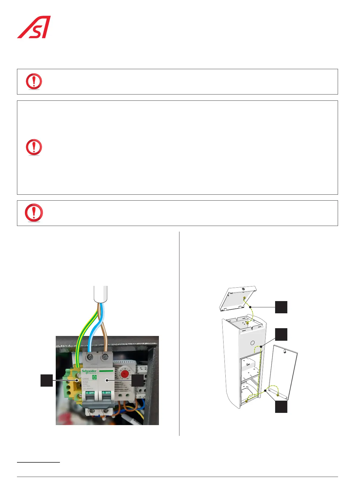
Connect the ground wires to their terminals:
• Cable (1) between the housing and the cover
(Check this connection before each closing of the cover);
• Cable (2) between the housing and the door
(Check this connection before each closing of the door);
• Cable (3) between the housing and the main terminal.
1920
1
3
2
Fig. 22 - Power supply connections Fig. 23 - Equipotential connections
1 Recommended power cable: 3G 2,5 mm². The power cable must comply with the technical specifications ( Chap. 9, page 43)
26
BL 229