• The following must be provided at the feeder head:
- Either a 10 A/300 mA differential circuit breaker (for five barriers maximum)
- Or a 10 A/30 mA super-immune selective differential circuit breaker (for one barrier maximum).
• Connect the various controls and options according to the diagram provided and without following the power cable that has
been moved from the board for this purpose.
ELECTROMAGNETIC COMPATIBILITY (EMC)
In order to avoid any deterioration in the operation of the equipment, please observe the following recommendations:
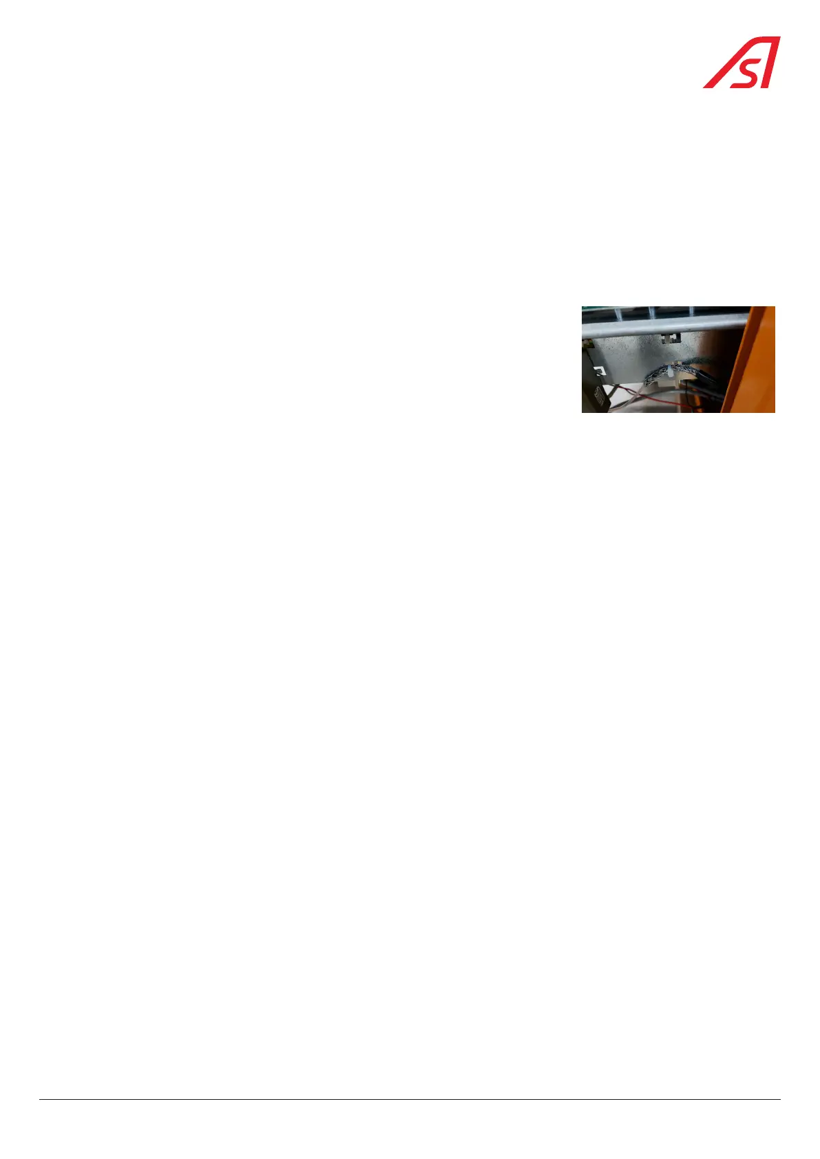
- Check the various connections of the equipotential bonding connections shown in Fig. 23 ;
- If the traffic lights option is used, place a ferrite 742 712 22 (1 turn) on the power supply
cable of the traffic lights in line with the hole in the shaft;
- If the traffic lights option is present, make a PE connection between the AS1049
board and the top cover (connection point present);
- If a receiver is used, the shield of the antenna cable must be taken from the board
directly next to the receiver;
- For the Ethernet connection, please use at least a shielded Category 5e F/UTP cable.
27
BL 229