5.3. OPERATION PRINCIPLE
The references in this chapter refer to the illustrations on Pages 8 & 9.
The opening of the arm (3) is controlled by the user (via a key switch, a push-button a radio transmitter), by detections loops
buried beneath the roadway, or by an external unit.
Closing is controlled in the same way, or automatically at the end of a time-out.
A STOP COMMAND IMMEDIATELY STOPS THE MOTOR, BUT NOT COMPLETELY THE ARM MOVEMENT: THE ARM COULD
LOWER PROGRESSIVELY DUE TO ITS WEIGHT AND ANGULAR POSITION.
THE "ANALOGUE POSITION SENSOR" ALLOWS TO ADJUST THE POSITION OF THE ARM AROUND THE STOP AND TO
COMPENSATE THIS PHENOMENON.
The movement created by the gear motor (19) is transmitted to the arm by a crankshaft-connecting rod device (18 + 20).
One or two balancing springs (12) assist the motor both at the opening and the closing of the barrier.
The speed of the arm’s movement, controlled by the frequency converter (26), is adjustable both at opening and at closing.
The movements are configured in the factory to offer progressive accelerations and controlled decelerations at the end of the
movement.
Safety
The barrier is put out of service when its movements are not completed within the assigned time or when it does not manage
to close after several attempts.
Presence sensors can optionally be added to open, stop immediately, reopen or close the arm if a user is detected in the
vicinity of the equipment.
In the open and closed positions, the alignment of the connecting rod and crankshaft (20 et 18) lock the arm’s movement
(“mechanical locking”).
The barrier is factory-configured to remain locked in the event of power failure, the boom arm then being raised by means of
the lever (28). However, this parameter can be modified so that the boom arm automatically rises in the event of a power failure.
In this case, it will rise to equilibrium with the balancing spring(s). The opening resulting angle will be close to 45°.
The complete opening of the barrier must be completed manually.
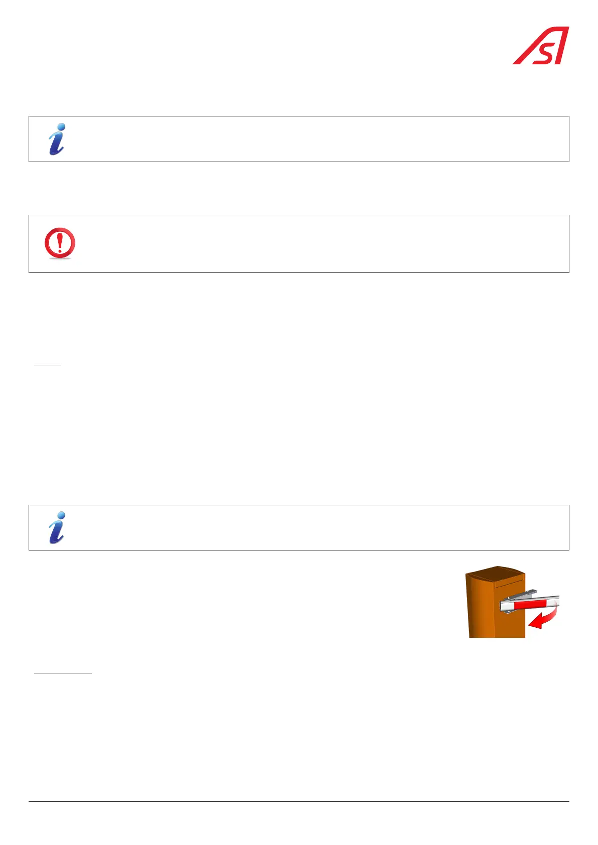
The boom arm swing-off device, which equips the BL 229 Toll as standard and is available as an
option for the BL 229 Standard, allows the boom arm to be unscrewed (the boom arm comes out of
its fastening jaw) when an impact occurs. The boom arm swing-off device avoids damage to the
barrier and the vehicle hitting it.
Fig. 3 - Swing-off device
Control board
The control board (25) co-ordinates the activity of the barrier: movement management, options, inputs and outputs, etc. This
information can however be repatriated and processed by an external terminal (not supplied by AS). The board records and
displays the history of the last operations carried out as well as any possible defects preventing the barrier’s movement.
5.4. CONTROL BOARD
See dedicated handbook.
11
BL 229