ARM
LENGTH
(M)
ARM TYPE OPTION
Ø OF
SPRING
WIRE
NB OF
SPRINGS
POSITION
OF
SPRINGS
ON LEVER
(1)
X
(2)
2,2
Round Ø 84 Rubber profile
5,5 1 A 54
2,5 5,5 1 C 40
3,0 7 1 A 56
3,5 7 1 B 29
4,0 7 2 A/A 58
4,5 7 2 A/A 40
5,0 7 2 B/B 28
4,0
Round Ø 84 Flexible mesh + boom arm light
7 2 A/A 50
4,5 7 2 B/B 34
3,0
Flat arm
5,5 1 C 37
3,0
Flat arm
Automatic opening when power fail 7 1 A 47
2,2
Flat arm
Driving part 1100 5,5 1 A 55
2,5 Driving part 1330 5,5 1 B 35
3,0 Driving part 1000 5,5 1 B 53
3,0 Driving part 1200 5,5 1 C 40
3,0 Driving part 1300 5,5 1 B 40
3,0
Oval arm
5,5 1 A 73
3,0
Oval arm
Automatic opening when power fail 5,5 1 C 46
3,0
Protecta
®
arm
5,5 1 B 39
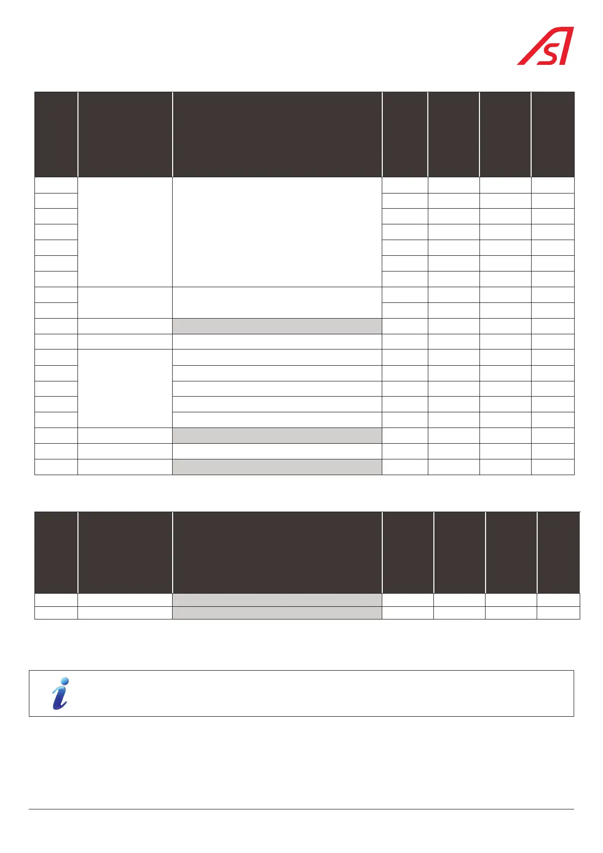
7.4. BALANCING TABLE FOR BL 229 TOLL(FOR INFORMATION ONLY)
ARM
LENGTH
(M)
ARM TYPE OPTION
Ø OF
SPRING
WIRE
NB OF
SPRINGS
POSITION
OF
SPRINGS
ON LEVER
(1)
X
(2)
3,0 Oval arm 5,5 1 C 45
3,0 Protecta
®
arm 5,5 1 B 39
(1) Spring position on lever: mark: (5) Fig. 26, page 29.
(2) X = Distance of fixing plate /support (mm): Fig. 27, page 29
For boom arms longer than 4 meters or for configurations with options, it can be useful to increase the torque on
the frequency converter (refer to the handbook of the AS1620 control unit).
31
BL 229