7.7. CALIBRATION OF THE ANALOG SENSOR
THE GATE WILL NOW MOVE TO DETERMINE THE UP AND DOWN POSITION!
1. Place the gate arm in the closed position;
2. Disconnect the RJ45 connector of the frequency converter to prevent gate arm from moving.
3. Adjust the analog sensor, it is located at 3 mm from the cam (or until the value shows 2000 (± 100) on the web interface
when the barrier is connected with the Ethernet port).
4. Plug the RJ45 connector of the frequency driver back in the control logic.
5. Perform the analog sensor calibration procedure.
For more information on the following steps, please refer to the technical manual of the AS1620 control logic.
7.7.1. USING THE MAINTENANCE INTERFACE
a. Go to the page Individual Tests and select the menu Calibration.
b. Perform the End stop position test.
c. The interface will confirm the success of the calibration if the gate arm is in the open position once the test is completed.
If calibration fails, return to step 3. The analog sensor is not correctly positioned.
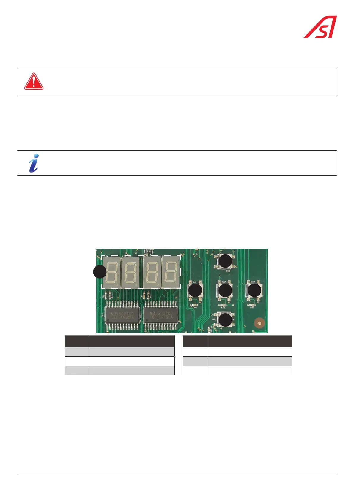
7.7.2. USING THE INTEGRATED HMI INTERFACE
1
5
3
4 2
6
REP. DESIGNATION REP. DESIGNATION
1 TOP button (SW5) 4 LEFT button (SW3)
2 RIGHT button (SW4) 5 OK button (SW7)
3 DOWN button (SW6) 6 Display
Fig. 35 - Integrated Human-Machine Interface
Proceed to the calibration of the analog sensor:
a. Press and hold the 'OK' (5) button for 2 seconds Set.
b. Press the up (1) and down (3) buttons until to find the menu: Inst
c. Press the up (1) and down (3) buttons until to find the menu: P0s
d. Press the right button (2) to display ang and again the right button two (2) seconds to display yes
e. Press and hold the right button for tree (3) seconds to start the calibration.
f. Check the test result to the display.
g. Press and hold the 'OK' (5) button for 2 seconds to leave the mode or wait 1 minute.
If calibration fails, return to step 3. The analog sensor is not correctly positioned.
35
BL 229