1 2 1 3 1 4 2 3 2 4 3 4
Turn (OFF) the power supply using the main circuit breaker (24).
Set upright the boom arm and remove it by unscrewing the three screws
and flat washers. (In reverse order of Chap. 6.4, page 21)
TAKE NOTE ABOUT THE POSITION OF THE SPRING (G) ON THE
SPRING LEVER (11) AS WELL AS DIMENSION OF X ( FIG. 24,
PAGE 28) BEFORE PROCEED TO THE NEXT STEP.
Unscrew the connecting rod lever (screws A) and the spring lever
(screws B).
Unscrew the compression screws (C) of the bearings on the arm shaft.
Withdraw the arm shaft (9).
Loosen the aluminium panel (4) of the boom arm side (pierced) and stick
a new one (full).
Remove the stop assembly (screws E).
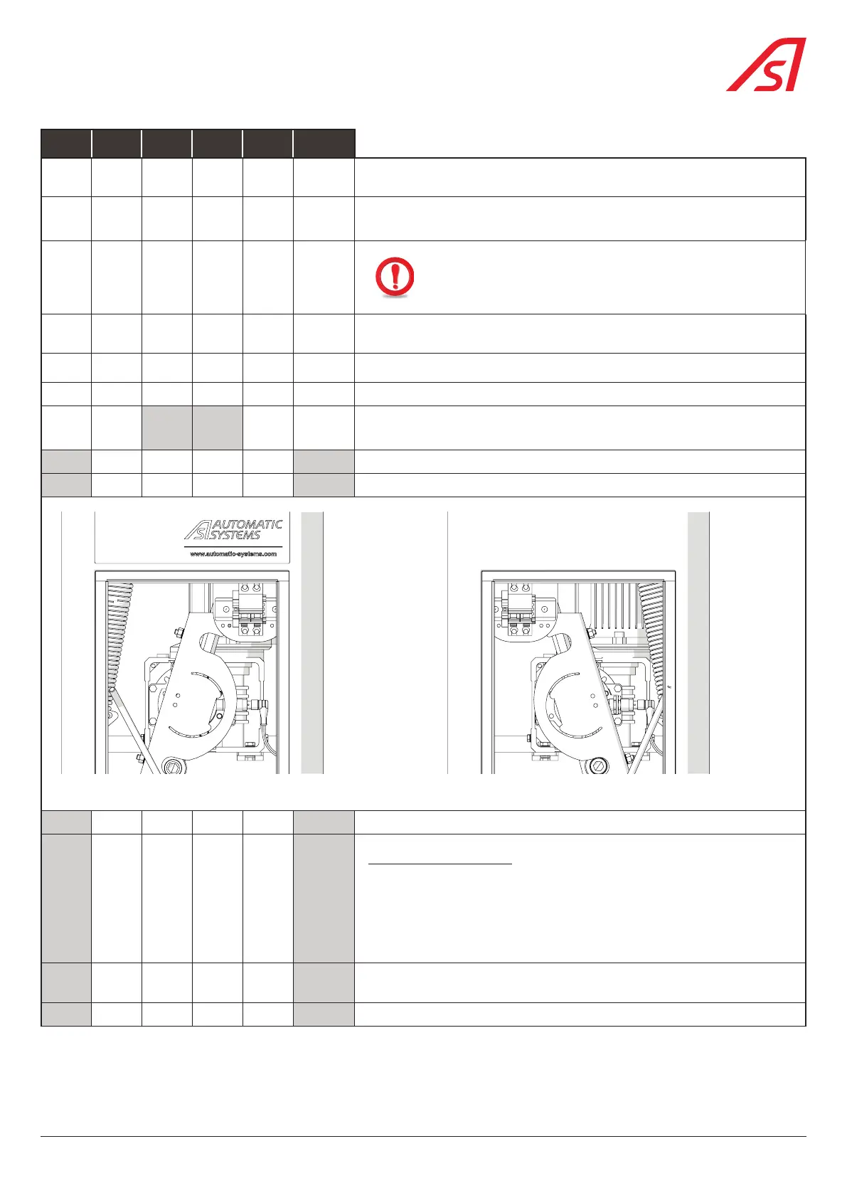
Reverse the position of the circuit breaker assembly (24).
Fig. 15 - Assembly solution 1/2 Fig. 16 - Assembly solution 3/4
Reverse the position of the unlocking lever (28).
Assembly the new stop:
Unscrew the 2 bumpers (K et L) to fix them on the new end stop unit.
Fix the new end stop unit by means of the screw (E). Add shims (provided)
if necessary, so that the cam (J) is correctly positioned in the notches
of the end stop unit.
Take care to slacken the spring to the maximum and to unscrew it from
its support (Nuts F) and from its lever (pivot G).
Unscrew the connecting rod from its lever (Screws H).
19
BL 229