22 XR Series Installation Instructions
4 Wiring
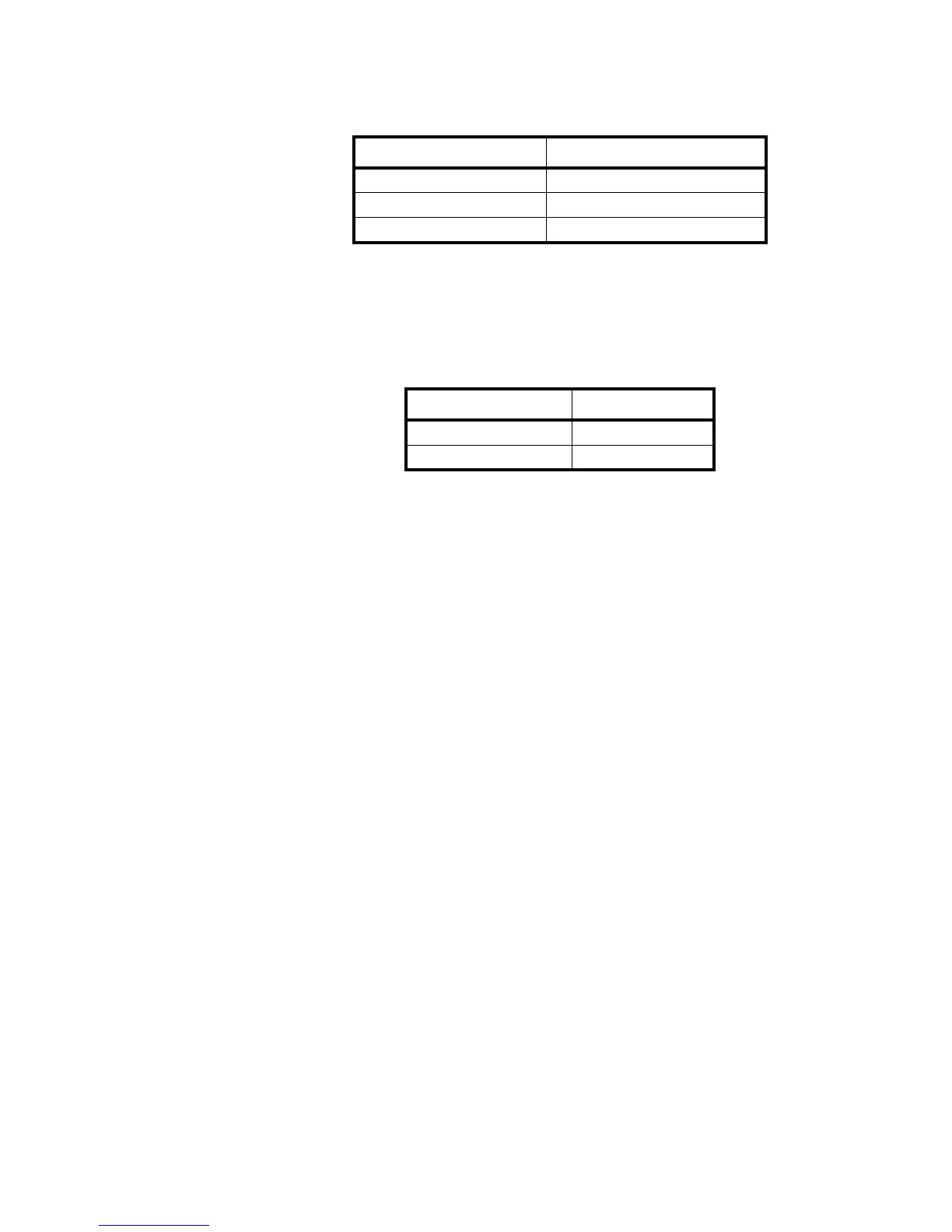
2. Terminate the indicator’s communication wires at the RS 232 terminal (J3).
See table below:
RS 422 Wiring
1. Set the Communication Input Jumper (JP 1) to RS422 / 485.
2. Terminate the indicator’s communication wires at the RS 422 / 485 terminal
(J4). See table below:
INDICATOR TO XR
TRANSMIT (TX) RECEIVE (RX)
RECEIVE (RX) NO CONNECTION
SIGNAL GROUND (GND) SIGNAL GROUND (SIG GND)
INDICATOR TO XR
TRANSMIT A (TX A) RECEIVE A (RX A)
TRANSMIT B (TX B) RECEIVE B (RX B)

 Loading...