XR Series Installation Instructions 23
4.2 Wiring the XR 2000
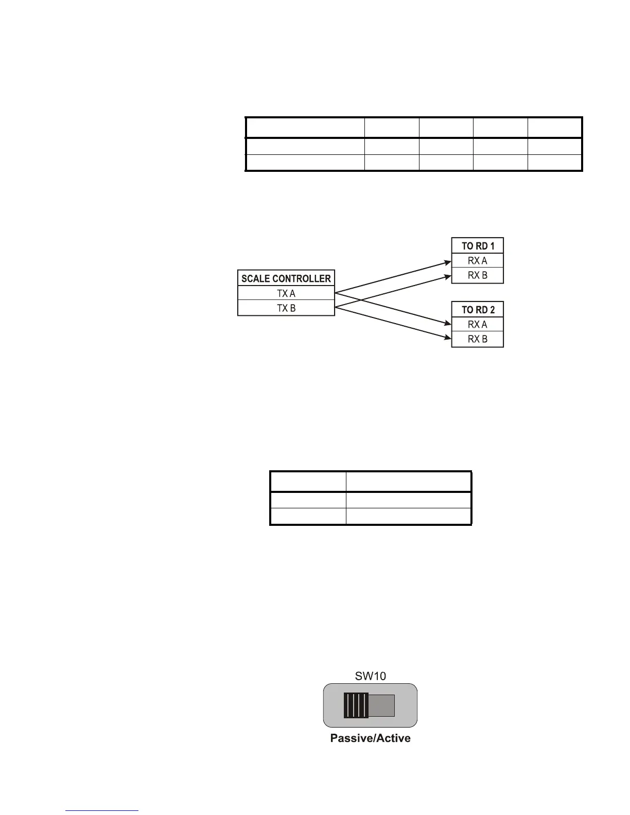
RS 485 Multi-Drop Wiring
Set the Communication Input Jumper (JP 1) to RS422 / 485.
Parallel Multi-drop wiring
Split Multi-Drop Wiring
Multi-Drop IDs are set using Parameter 1.4: Multi-Drop ID on page 32.
20 mA Current Loop Wiring
1. Set the Communication Input Jumper (JP 1) to 20mA LOOP.
2. Terminate the indicator’s communication wires at the 20 mA Current Loop
terminal (J5). See table below:
20 mA Current Loop Mode Switch
l After the current loop is wired, ACTIVE or PASSIVE mode must be selected
(SW 10) on the controller board.
l Select Active mode if the XR is required to supply the current to the
communicating device.
l Select Passive mode if the communicating device (indicator) supplies the
current to the XR.
l If unsure of these requirements, check the device’s manual.
SCALE CONTROLLER TO RD 1 TO RD 2 TO RD 3 ETC.
TX A RX A RX A RX A RX A
TX B RX B RX B RX B RX B
INDICATOR TO XR
20 mA TX + RECEIVE POSITIVE (RX +)
20 mA TX - RECEIVE NEGATIVE (RX -)
 Loading...