S6L Network Connections 31
Making S6L Network Connections
After connecting power and peripherals, make audio network connections between system components. Audio network connec-
tions must follow a small number of guidelines, described below and in the example configuration diagrams.
1. Redundant Ring Network
In a redundant ring network, components are daisy-chained together in a “closed ring” using the Network ports on each device. All
S6L systems must be connected in a redundant ring network as shown in this guide.
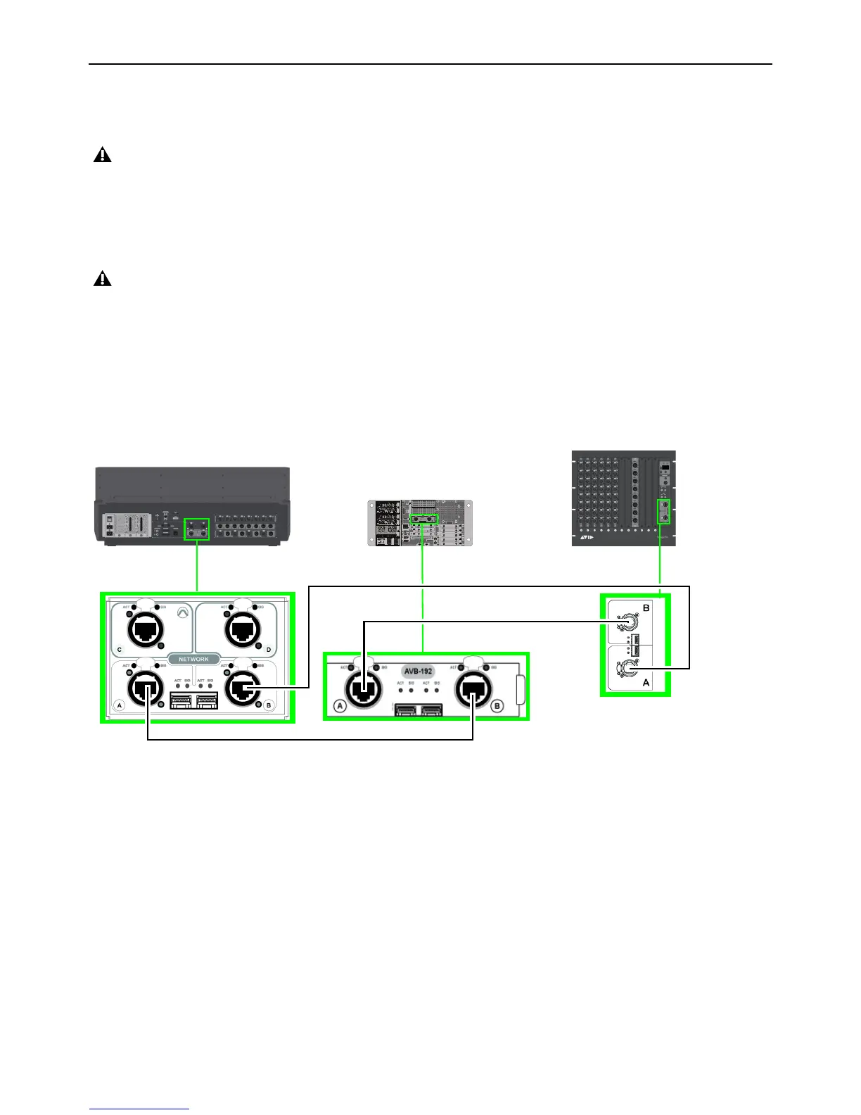
2. “A’ to “B” (Network Port Connections)
All S6L network connections go between an “A” port and a “B” port:
For example, in a base configuration single system, connect S6L Network port
A to E6L port Master port B, E6L Master port A to
Stage IO unit port
B, and Stage IO unit(s) port A to S6L port B. (In Figure 1, the redundant ring is established by the connection
from the Stage I/O unit port
A back to the S6L control surface network port B.)
If you are setting up your S6L system for the first time, before connecting system components make sure to install the latest System
Restore software on your S6L control surface and E6L engine as explained in
VENUE System Restore.
Do not connect network equipment such as routers, hubs and switches to any S6L system Network ports.
Figure 1. Network port connections (A to B) between S6L control surface (at left), E6L engine (middle), and Stage 64 (at right)
IN
OUT
NETWORK
MASTER 1
WORD CLOCK
UTIL
EXPANSION
2
3
6
7
8
1
2
3
4
5
OKOK
A
B
AVB-192
ACT SIG ACT SIG
ACT SIG ACT SIG
A
B
S6L control surface
E6L engine
Stage I/O unit