page11.
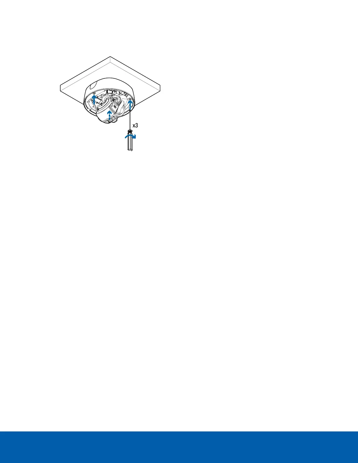
3. Mount the camera using the three mounting setscrews.
Connecting Cables
Refer to the diagrams in Overview on page1 for the location of the different connectors.
1. If external input or output devices are part of the installation (for example: door contacts, relays, etc.),
connect the devices to the I/O connector block.
2. Connect a network cable to the Ethernet port (RJ-45 connector).
The Link LED indicator will turn on once a network link has been established.
3. Connect power using one of the following methods:
l
Power over Ethernet (PoE) Class 3 or Class 4 — If PoE is available, the LEDs will turn on.
l
External Power — Connect an external 12 V DC power source to the power connector block.
4. Check that the Connection Status LED indicator indicates the correct state. For more information, see
Connection Status LED Indicator on page48.
Installing the Dome Cover
Be careful not to touch or scratch the dome bubble when installing the dome cover.
Installing the Dome Cover for a Non-IR Dome Camera
1. Attach the lanyard to the dome cover.
2. Remove the protective cover on the inside of the dome bubble.
3. Attach the dome cover to the base by tightening the screws with the star-shaped driver.
4. Remove the protective cover on the outside of the dome bubble.
Connecting Cables 17
 Loading...