Connecting Cables
Refer to the diagrams in the Overview section for the location of the different connectors.
To connect the cables required for proper operation, complete the following:
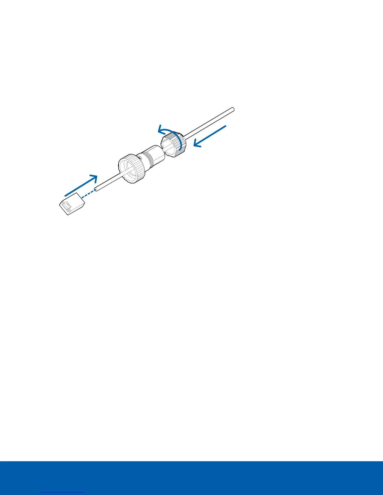
1. Feed the network cable through the gland cap and cable gland. Crimp the RJ-45 cable connector
(supplied) to the end of your network cable.
The network cable connection can also be used to supply power to the camera using Power over
Ethernet (PoE). If using PoE, connect a PoE compliant injector or switch to the Ethernet network cable
with the output rated:
l With IR Ring: Microsemi PD9601G/AC (90 W) or Microsemi PD9501GR/AC (60 W) Power over
Ethernet mid-span injector.
l Without IR Ring: 25.5 W PoE+, IEEE802.3at Type 2 PoE+.
2. Connect the following optional connections to the supplied pigtail I/O connector. See Connecting to
Power, Audio, and External Devices on page59 for more information on the different connections.
Connecting Cables 21

 Loading...