Wiring Audio, I/O, and AUX Power
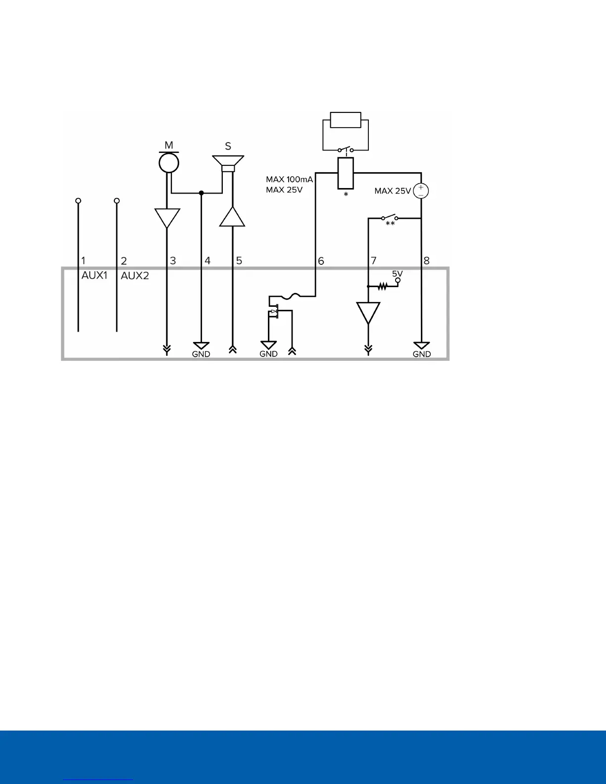
The connections for the I/O, audio, and power wires is shown in the following diagram:
1. Brown — AUX1 Auxiliary Power wire, accepts either polarity
2. Blue — AUX2 Auxiliary Power wire, accepts either polarity
3. Brown — Audio Input (line level)
An external power amplifier should be used when connecting speakers and microphones, as shown in
the diagram.
4. Yellow — Audio Ground return
5. Green — Audio Output (line level)
6. Purple — Relay Output: When active, Output is internally connected with the Ground. Circuit is open when
inactive. Maximum load is 25 V DC, 100 mA.
7. Gray — Relay Ground return
8. Red — Relay Input: To activate, connect the Input to the Ground wire. To deactivate, leave it
disconnected or apply between 3-15 V.
l * — Relay
l ** — Switch
l M — Microphone
l S — Speaker
l AUX1 — Brown Auxiliary Power wire
l AUX2 — Blue Auxiliary Power wire
Wiring Audio, I/O, and AUX Power 60
 Loading...