Cable Connections
Connecting to Power, Audio, and External Devices
If PoE is not available, the camera may be powered through the auxiliary power cable using either 12V DC or
24V AC. The power consumption information is listed in the product specifications.
To power the camera, connect the two power wires to the brown and blue auxiliary power wires. The
connection can be made with either polarity.
WARNING — This product is intended to be supplied by a UL Listed Power Unit marked “Class 2” or
“LPS” or “Limited Power Source” with output rated:
l With IR LEDs: 24V AC ± 10%, 74 VA minimum, or 24 V DC ± 10%, 52 W minimum, or a Microsemi
PD9601G/AC (90 W) or Microsemi PD9501GR/AC (60 W) Power over Ethernet mid-span injector.
l Without IR LEDs: 24V AC ± 10%, 37 VA minimum, or 24 V DC ± 10%, 26 W minimum, or PoE+
IEEE802.3at Type 2 compliant Power Sourcing Equipment (PSE) rated 50-57 V DC, 25.5 W
minimum.
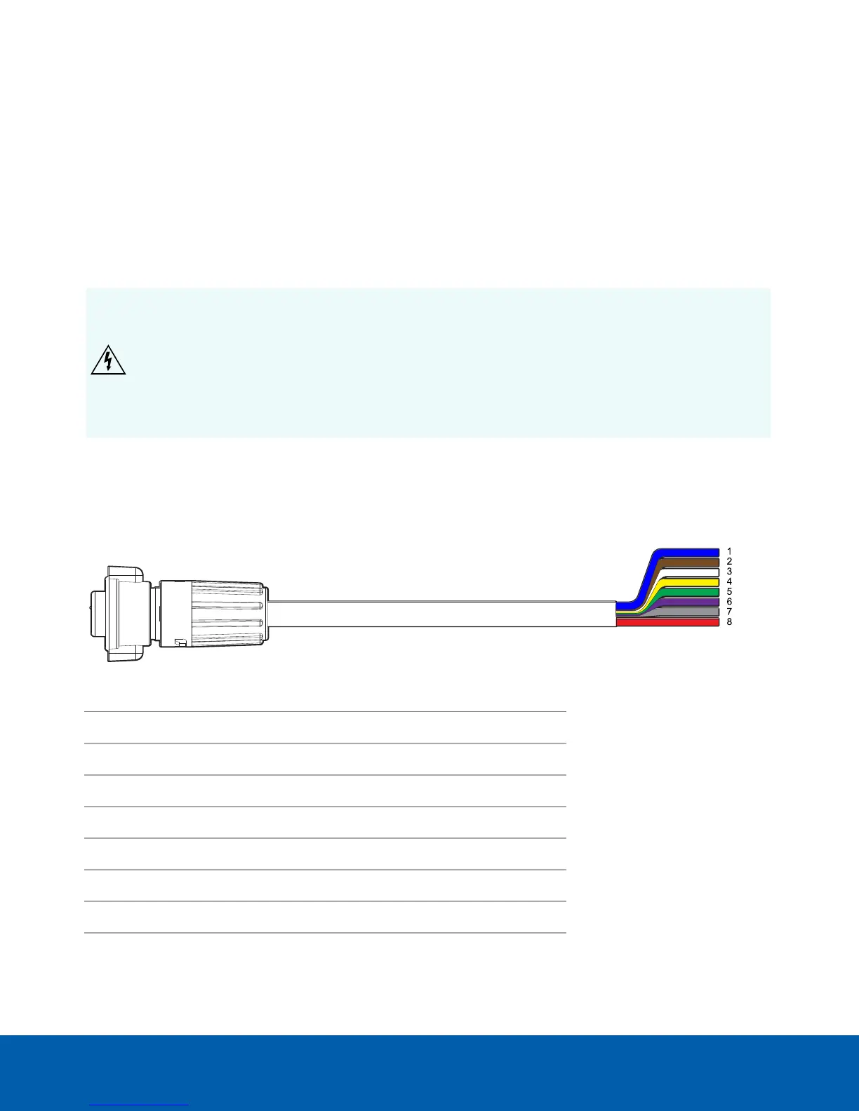
Pigtail Connector and Wires
Power supplies, audio devices, and external devices are connected to the camera through the power, audio,
and I/O pigtail. The following diagram and table shows the I/O, audio, and power pigtail connector and wires:
Wire Color Description
1 Blue AUX1 Power, accepts either polarity
2 Brown AUX2 Power, accepts either polarity
3 White Audio IN
4 Yellow Audio GND
5 Green Audio OUT
6 Purple Relay OUT
7 Gray Relay GND
8 Pink Relay IN
Cable Connections 59
 Loading...