Oxygen 5
Pag. 13
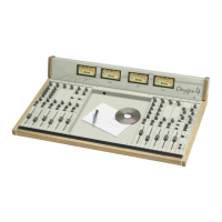
3.6 GAIN INPUT A TRIMMER
You can use the multi-turns trimmer to fit the Micro level to the input level of the pre-
amplification circuit. It’s highly recommended if the Gain potentiometer doesn’t amplify or
attenuate enough the Micro signal. Adjust the trimmer to reach the 0 dB PFL output level
corresponding to the Gain control central position (read the level on the VU-Meter).
Remember that through jumper setting you can change the input A gain to fit the Micro
level or the Line level (see § 0).
We suggest to use the Input A for Micro signals and the B for the Line signals.
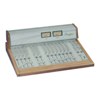
3.7 A-B INPUT SELECTOR
It selects the input A (led switched off) without the pressed button; the input B (led
switched on) with the pressed button.
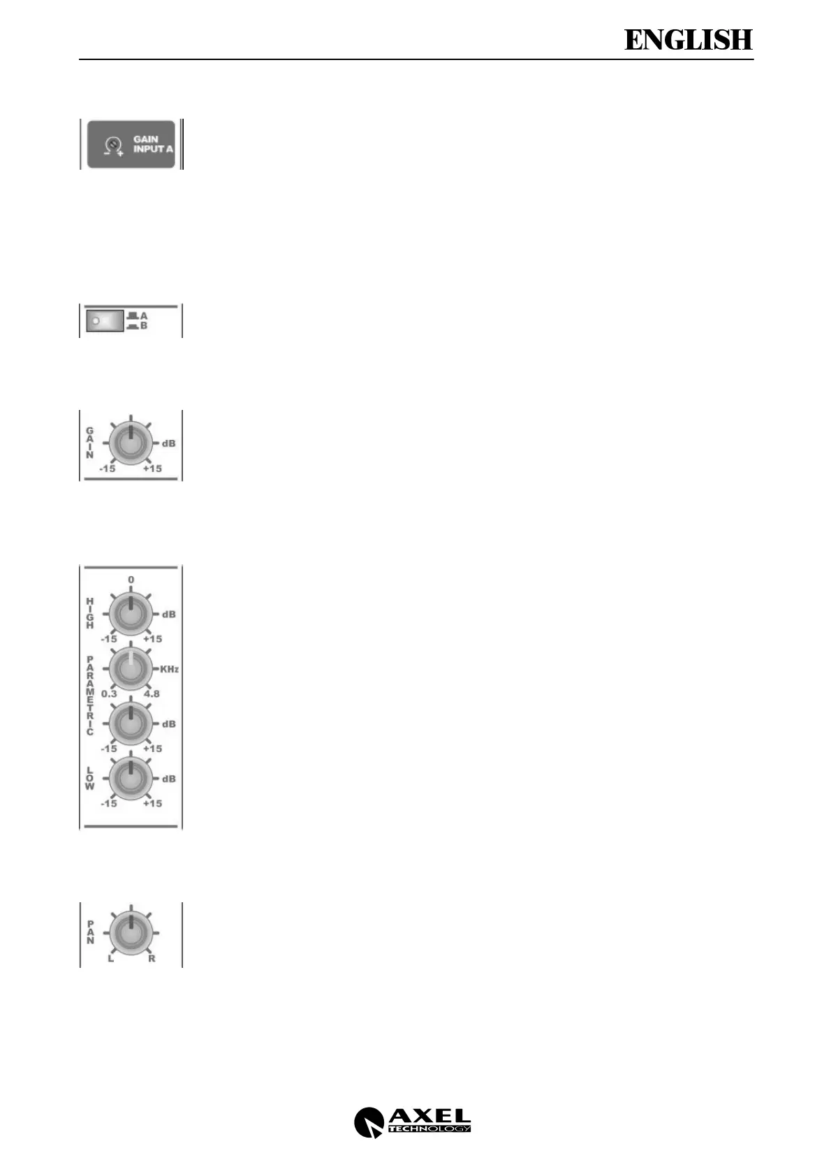
3.8 GAIN CONTROL
It sets the gain from –15dB to + 15dB on the selected input (A or B).
Set the gain so that:
• the output audio signal is not distorted when the slider is on its upper point
• the PFL level is 0 dB
3.9 EQUALIZATION SECTION
The equalisation section is based on three controls: LOW, MID, HIGH (ranging from
±15dB).
In particular, you can modify the Middle frequencies between 0.3 and 4.8 KHz (central
position: 1 KHz).
You can get a flat frequency response when the potentiometers are in their central
position (underlined by a ‘click’).
3.10 PANPOT CONTROL
The PAN control allows sound balancing between Left and Right output channels. In the
central position the gain is 0 dB for both channels.
 Loading...