Oxygen 5
Pag. 26
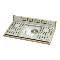
Pin-out SUB D 9P female:
Pin 1 GND
Enables the Talk Back function if you
supplies + 6 V
DC DUCK: by feeding a 0 ÷ 6 V tension
you can control the Sub VCA
Pin 4 N.C.
Pin 5 N.C.
Pin 6 supplies + 6V
switchs the Mono modules into the ON
state if you supply + 6 V
Emitter of the photocoupled transistor for
ON state signalling
Pin 9 Collector of the photocoupled transistor for
ON state signalling
THE CONNECTOR SUPPLIES THE FOLLOWING VOLTAGES:
• + 6 VDC (pin 6)
• GND (pin 1)
These voltages can be used to polarize external optoisolator devices. We suggest to use a
100Ω (or more) resistor in series connection with the phototransistor emitter to prevent the
risk of damages to the photocoupler, due to extra-high current.
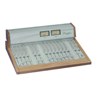
5.4 EXTERNAL IN INPUT
You can link to the EXT IN an external (line level) signal. This signal, faded by the Ext
Gain control, can be sent to the Master module output (add to the other output signals) or
listened by pressing the related selections in the Control Room / Studio section.
The two input (mono) connectors are electronically balanced on female Jack with 0 dB
gain. The pin-out presents standard configuration:
• Sleeve Ground
• Tip Signal
• Ring Return
We suggest to use balanced links. See Appendix A for wire connection schemes
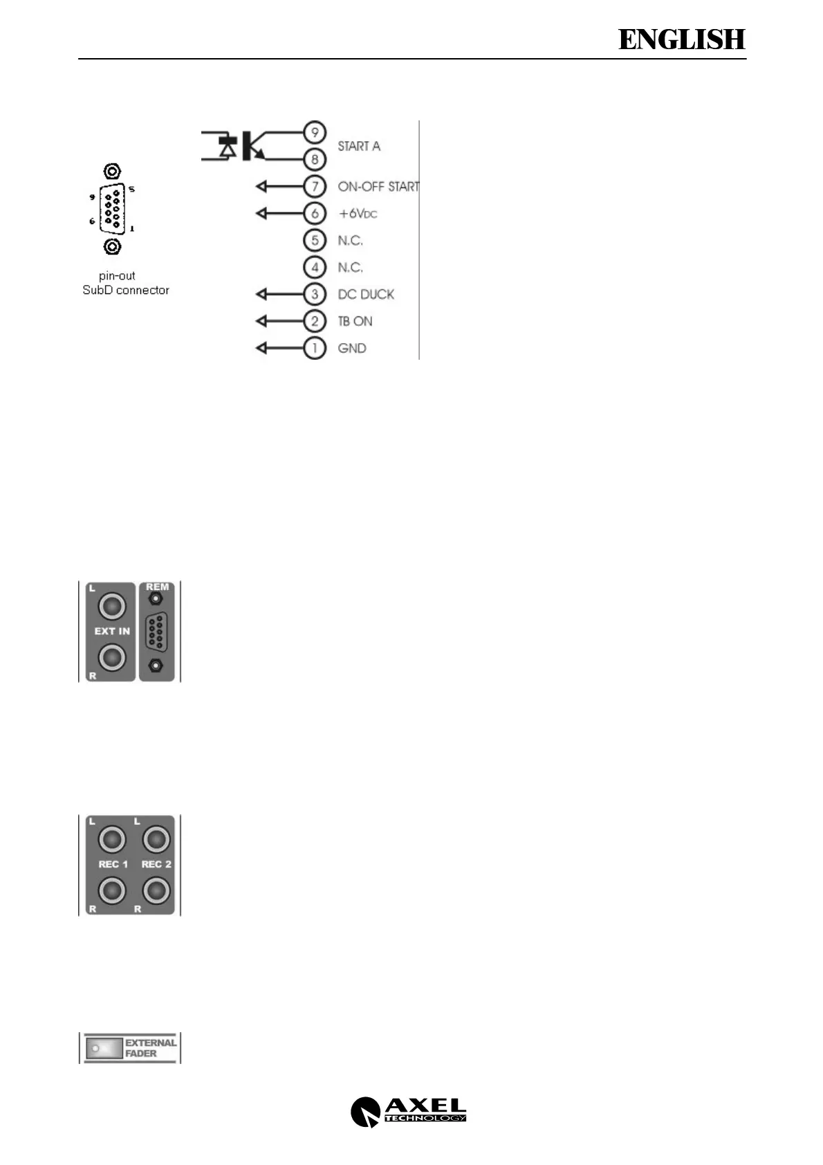
5.5 REC OUT OUTPUT
REC OUT sockets provide (also separately) the Sub signal or the Master signal
(depending on the internal jumper configuration).
Each output connectors is electronically balanced on female Jack with 0 dB gain.
The pin-out presents standard configuration:
• Sleeve Ground
• Tip Signal
• Ring Return
We suggest to use balanced links. See Appendix A for wire connection schemes
5.6 EXTERNAL FADER SWITCH
The EXTERNAL FADER switch enables the control of Sub fading function by an external
slider. For this purpose is optionally available the DJ Console equipment, that allows:
• The On/Off Mono modules remote control (if modules are properly set).
 Loading...