Oxygen 5
Pag. 38
8 VU METER
8.1 MIXER CONNECTION
The MET connector placed on Master module transfers the supply voltages and the
signals feeding the VU-METER and the (optional) TIMERs.
The connector type is SubD- 9 female. Please make sure the Met connector is on site.
8.2 VU-METER OPERATION
The two VU-Meter on the mixer cover show the Right and Left channel output level till a
PFL is called by a module. In this case, the VU-Meter will show the PFL signal.
Every Vu Meter includes also a peak meter with red led placed behind the ‘+’ symbol on
the dB scale.
The led blinks every time a signal peak reaches the 0 dB level (the factory pre-set meter
setting is based on a 1 KHz sinusoidal, static signal so that the led switches on when the
indicator exceed 0 dB level).
Please note that, due to its mechanical inertial, the Vu Meter mechanical pointers show
only the medium signal value (a few dB lower that the related peak value).
Mechanical Vu meter levels are not adjustable.
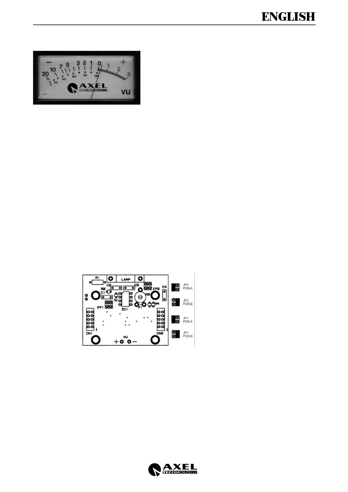
Every Vu Meter board (placed behind the
instrument, under the console cover)
presents two jumper settings:
• The first (JP1) allows to assign the Vu
Meter to the Right (Pos B) or to the Left
(Pos A) channel.
• The second (JP2) allows to use the
peak meter (red led) in the adjustable
mode or fixed mode (factory pre-set
peak level)
JP2 on Pos A: you can modify the peak
level through the P1 trimmer
JP2 on Pos B: peak level factory pre-
set on 0 dB and not adjustable
 Loading...