Oxygen 5
Pag. 20
THE CONNECTOR SUPPLIES THE FOLLOWING VOLTAGES:
• + 6 VDC (pin 6)
• GND (pin 1)
These voltages can be used to polarize external optoisolator devices. We suggest to use a
100Ω (or more) resistor in series connection with the phototransistor emitter to prevent the
risk of damages to the photocoupler, due to extra-high current.
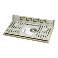
4.4 REC OUT OUTPUT
Depending on the internal jumper setting, REC OUT connector (mono-balanced) provides:
§ the only signal incoming from the telephone line (Receive signal)
• the only signal outgoing to the telephone line (Send signal)
• the sum of two signals.
The REC OUT signal (mono) is electronically balanced on female Jack with 0 dB gain.
The pin-out presents standard configuration:
• Sleeve Ground
• Tip Signal
• Ring Return
We suggest to use balanced links. See Appendix A for wire connection schemes
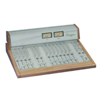
4.5 SEND GAIN CONTROL
It sets the gain from -15dB to + 15dB of the signal send to the telephone line.
4.6 RECEIVE GAIN CONTROL
It sets the gain from -15dB to + 15dB of the signal received from the telephone line.
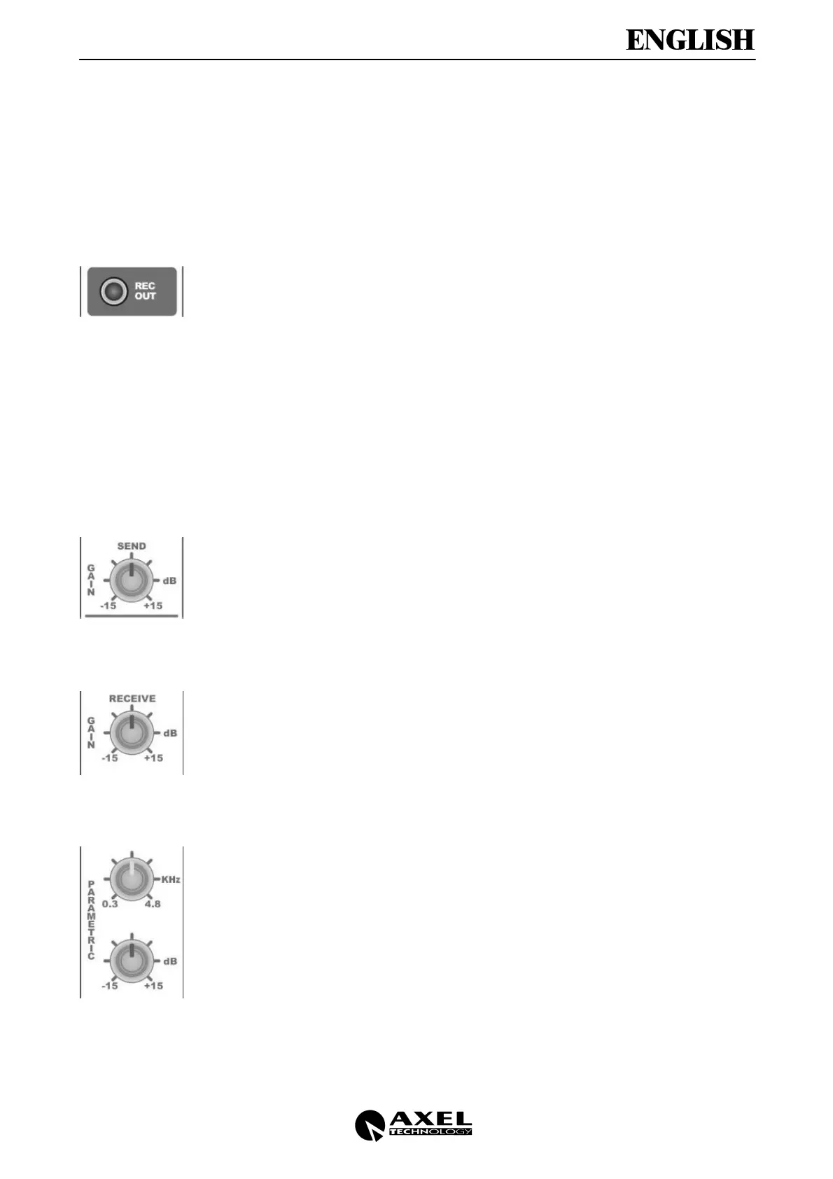
4.7 EQUALIZATION SECTION
The equalisation section is based on the MID control operating from ± 15dB.
In particular, you can vary the operation frequencies of Mid control between 0.3 and 4.8
KHz (central position: 1 KHz).
You can get a flat frequency response when the potentiometers are in their central
position (underlined by a ‘click’).
 Loading...