Oxygen 5
Pag. 7
Please note that:
§ the max current value provided by the Start/Stop photo transistors is 20 mA.
§ Interface phototransistors are not able to directly drive any external relais. Please use
them to drive an external power transistor .
§ Internal phototransistor impedance is about 150 Ω.
§ To group Start/Stop commands, please join pins 7 and 2 + 6 and 1
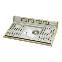
Pin-out SUB D 9P female in INDIRECT mode:
Emitter of the photocoupled transistor
for START function
Collector of the photocoupled
transistor for START function
enables the PFL function if you supply
+ 6 V and disables it if you supply – 6V
Pin 4 Supplies - 6V
Supplies + 6V when B input is selected
Emitter of the photocoupled transistor
for STOP function
Collector of the photocoupled
transistor for STOP function
Pin 8 GND
Supplies + 6V when A input is selected
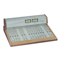
2) DIRECT Mode (referred to the ‘Switch/Led’ jumper configuration in the scheme showed
at the end of this chapter)
Through jumper setting you can directly link the electrical connections of the Start/Stop
button to the Remote interface (pins 1-2).
The pins 6-7 are directly linked to the red led next to the Start/Stop button (led current is
about 5 mA). This mode can be used to visualise on the module the READY state of an
external equipment and is frequently when turntable are driven.
Pin-out SUB D 9P female in DIRECT mode:
Pin 1 1° contact of the Start/Stop button
Pin 2 2° contact of the Start/Stop button
enables the PFL function if you supply
+ 6 V and disables it if you supply – 6V
Pin 4 Supplies - 6V
Supplies + 6V when B input is selected
Pin 6 Anode of Start/Stop led
Pin 7 Cathode of Start/Stop led
Pin 8 GND
Supplies + 6V when A input is selected
PFL ACCESS MODE (pin 3)
The PFL ACCESS mode allows the remote enabling of the pre-listening function. You just
need to supply + 6V to enable the function and – 6V to disable it.
A/B INPUT SELECTION SIGNALLING
The signalling of the selected input is available on the interface (pins 5 and 9). if the pin 9
is on +6V state, the A input is selected; if the pin 5 is on +6V state, the B input is selected.
REMOTE CONNECTOR SUPPLIES THE FOLLOWING VOLTAGES:
• -6 VDC (pin 4)
• GND (pin 8)
These voltages can be used to polarize the optoisolator devices. We suggest to use a
100Ω (or more) resistor in series connection with the phototransistor emitter to prevent the
risk of damages to the photocoupler, due to extra-high current.
 Loading...