1-2
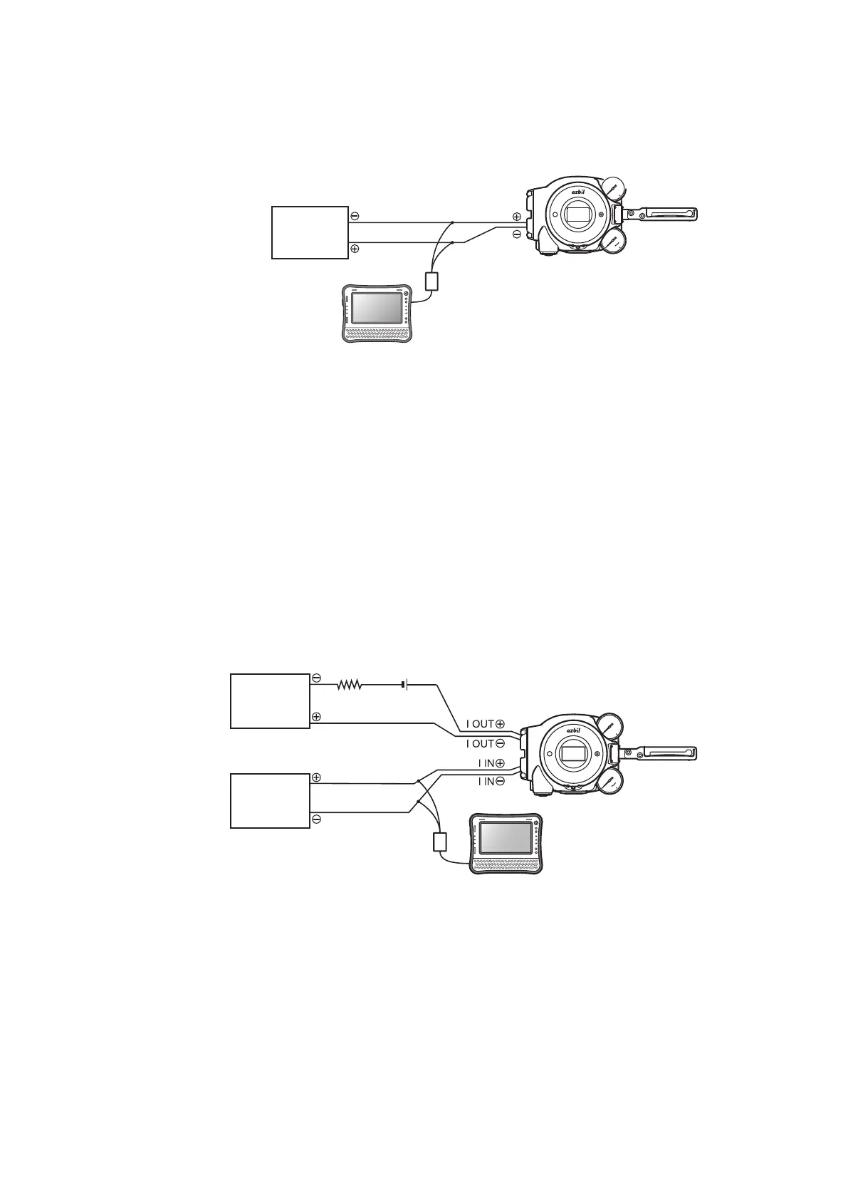
1-2 System Configuration without Motion Transmission
This shows the configuration for a system that does not use the motion transmission
function of this device (model AVP702).
Host
controller
DC4–20mA
I IN
I IN
HART Modem
Device
HART configuration
tool
Figure1-2 System Configuration without Motion Transmission (Model AVP702)
1-3 System Configuration with Motion Transmission
This device (model AVP701) has a function for motion transmission of the control valve.
To output the travel signal to the host monitoring device using analog values, configure
the system with motion transmission. Normally, the travel from fully closed to fully open
are output as 4–20 mA DC.
This shows an example of a system configuration for outputting valve travels detected
with this device as 4–20 mA DC analog signals.
With this system configuration, analog signals are output directly to the higher-order host
monitoring system from this device.
Device
Analog signal
DC4–20mA
DC4–20mA
Host
controller
Host
monitoring
system
(current input)
HART Modem
HART configuration tool
250Ω
Resistor
DC24V
Power supply
*1 *1
*1: For the detailed information of the power supply and resistor, please
refer to the figure 2-18 of 2-3-4 Input Signals and Travel Transmission
Figure1-3 System Configuration with Motion Transmission (Model AVP701)

 Loading...
