1-1
Chapter 1 Structure of the 700 Series Control System
This chapter describes the device configuration of the control system that uses the
device.
• Description of the configuration of the input/output system in the device
• Description of the structure of the main unit of the device and the name and function of
each part
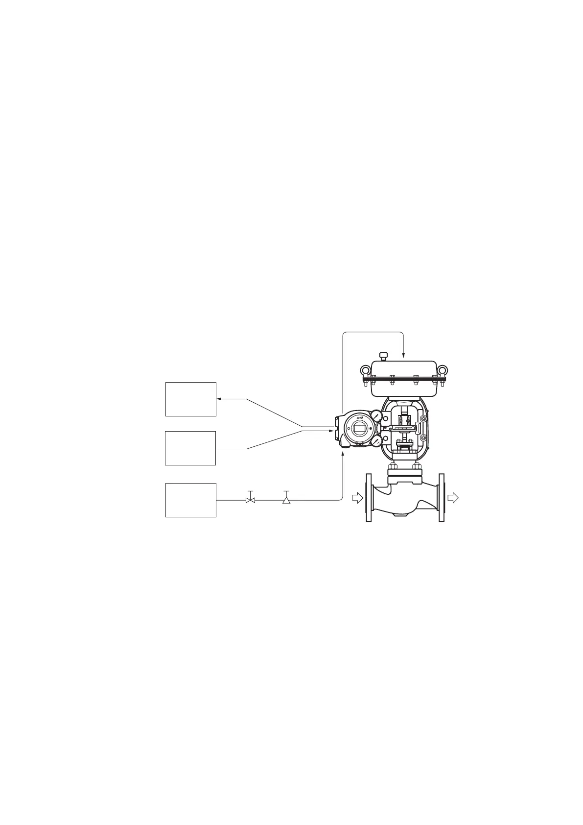
1-1 System Configuration
This device is a smart valve positioner that can be connected to the 4–20 mA DC signal
lines of the controller output. It makes various adjustments using electricity, so the
relationship between input signals and control valve travel can be set to any desired
value. In addition, by connecting the device using four lines, the control valve travel is
transmitted to the host monitoring system as a 4–20 mA DC analog signal. (Only the
AVP701 model supports valve travel transmission.)
Host
monitoring
system
Air supply
system
Host controller
DC4–20mA analog signal
DC4–20mA analog signal
(AVP701)
Shutoff Solenoid valve
with filter
Supply air
Device
Air to the actuator
Control valve
Process fluid
valve
Figure1-1 Concept Diagram of the 700 Series Control System

 Loading...
